a.
Set the energy range within the Amp Parameter Setup section. For
example, 10keV for a range of 0 - 10keV; 20keV for a range of 0 -
20keV, etc. Choose the lowest range that covers your application’s
energy range of interest.
b.
Within the SCA Parameter Setup section, enter the energy of the test
calibration source in the centroid entry field for SCA #1 (for example,
5.894keV for
55
Fe).
c.
Next enter the desired SCA window width for SCA #1 in the width
entry field. Set the window width to 2-3 times the expected FWHM
detector resolution (for example, if under general operating
conditions, the expected FWHM is 150eV, set the width to 0.300keV.
d.
Enable the output for SCA #1 by checking the check box (this is
selected by default when this screen is presented). Note also that the
Apply to all Amp/TCAs check box at the bottom of the screen should
not be selected at this time.
e.
Press the SET button.
f.
Adjust the fine gain on the selected 2016 module to center the
calibration peak within the SCA window as viewed on the MVC
window.
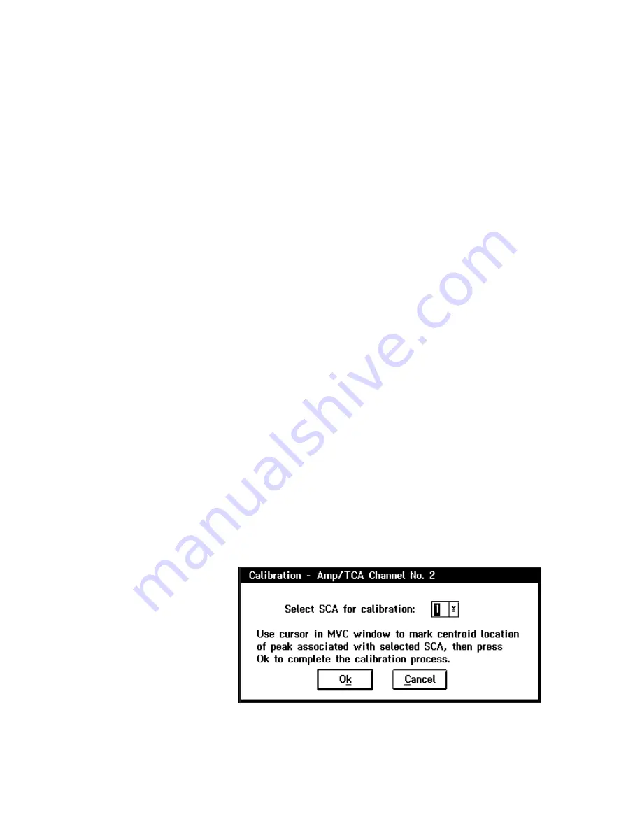
g.
Once the peak has been properly centered, press the Ok button. You
will now be presented with the screen shown in Figure 16. As noted
on this screen, use the cursor in the MVC window to mark the peak
location (centroid). When done, press Ok (make sure you have
selected SCA #1).
21
Calibration Procedure
Figure 16 Choosing the SCA to Calibrate