Canarm PENTA-LITE 6LEC Series Скачать руководство пользователя страница 14

14 

Canarm Hexa-Lite 6LEC Series - 10’-24' Models

MOUNTING METHOD 2: ANGLE IRONS

6.4b Fasten Double Angle Irons to Roof Structure Mounting Points:

ATTENTION: 

Do not tighten the hardware until the upper yoke has been mounted to the angle irons.

Proceed to step 6.5.

Grade 5 Hardware (customer supplied):

a.

 (4) 1/2”-13 GR 5 Bolt

b.

 (8) 1/2” Flat Washer

c. 

(4) 2-1/2” Square Washer (see diagram)

d.

 (4) 1/2” Nylock Nut

Do not install the fan from a single purlin, truss, or bar joist.

Ne pas installer le ventilateur à partir d’une même purlin, botte, ou solives.

The angle irons must be fastened to the roof structure at each end.

Les cornières doivent être attachés à la structure de toit à chaque extrémité.

Fasten the angle irons to the roof structure mounting points at each end with customer-supplied Grade 8 

hardware as shown.

Fixer les cornières à la structure du toit de points de fixation à chaque extrémité fourni par le client 

matérielle la 8e année, comme illustré.

CAUTION/ATTENTION

!

Содержание PENTA-LITE 6LEC Series

Страница 1: ...HEXA LITE FANS 6LEC SERIES 10 24 Models INSTALLATION MANUAL Custom Designed Reduced Maintenance STOL Technology Patent pending...

Страница 2: ...nce with all applicable codes and standards including fire rated construction Failure to comply could result in personal injury electric shock death fire and or property damage Before attempting insta...

Страница 3: ...es pr vues par le fabricant This unit has an unguarded impeller Do not use in locations readily accessible to people or animals Cet appareil poss de une roue sans surveillance Ne pas utiliser dans des...

Страница 4: ...lbs 50 kg 6L16EC V P 16 4 9M Fan 24 610mm 96 2438mm 17 432mm 120 lbs 55 kg 6L18EC V P 18 5 5M Fan 24 610mm 108 2743mm 17 432mm 140 lbs 64 kg 6L20EC V P 20 6 1M Fan 24 610mm 120 3048mm 17 432mm 150 lb...

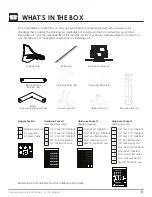
Страница 5: ...alling unit Wingtips x6 Blade x6 Motor Chassis x1 5 Gripple Fasteners 4 15 Guy Wires 1 5 Safety Cable Gripple Packet Reference Controller Brochure for additional hardware 4 1 2 13x3 1 2 GR5 Bolt 4 1 2...

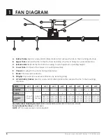
Страница 6: ...the chassis to mounting assembly E Chassis Housing for the motor and gear reducer F Blade Provides air movement G Wingtip Improves air movement efficiency by reducing drag H 4 Point Safety Cables Use...

Страница 7: ...nting the fan closer than 15 of its diameter to any object or its path If this is an issue mounting extension bars and smaller fans are available from Canarm 2 3 Fire Suppression Systems and Fan Place...

Страница 8: ...oper installation of Safety Cables These are supplied with every fan You must install safety cable for warranty to be in effect 3 4 Guy Wires While in operation a fan can sway due to minor imbalance o...

Страница 9: ...he equipment The spacing between multiple fans should be no less than 2 5x the fans diameter when measured from the center of the fans The mounting structure must be able to withstand the torque which...

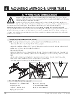
Страница 10: ...for fan installation Canarm recommends consulting with a structural engineer prior to fan installation Aider directement la structure du b timent Toutes les instructions de montage supposent que la st...

Страница 11: ...EMENT Do not install the fan from a single purlin truss or bar joist Ne pas installer le ventilateur partir d une seule panne botte ou solives Unsupported angle iron spans should not exceed 12 3 7m No...

Страница 12: ...Angle Irons Together if span is longer than 8 If the angle iron span is 8 2 4m or less proceed to step 6 4a on the following page If the angle iron span is longer than 8 2 4m it is necessary to use d...

Страница 13: ...Square Washer see diagram d 4 1 2 Nylock Nut 2 5 6 4 cm 9 16 Dia 1 4 cm 2 5 6 4 cm Do not install the fan from a single purlin truss or bar joist Ne pas installer le ventilateur partir d une m me pur...

Страница 14: ...4 1 2 Nylock Nut Do not install the fan from a single purlin truss or bar joist Ne pas installer le ventilateur partir d une m me purlin botte ou solives The angle irons must be fastened to the roof...

Страница 15: ...t Washer c 4 1 2 13 Nylock Nut a b b c Upper Yoke Side View The angle irons should be aligned with the outermost holes of the upper yoke Les corni res devraient tre align es avec les trous ext rieurs...

Страница 16: ...be placed on both sides of the plate for each bolt 6 9 Pre Drill Angle Iron Brackets Holes Your angle iron should be cut to allow 1 2 1 27 cm clearance between the end of the angle iron and the purlin...

Страница 17: ...to the outside faces of the purlin brackets 6 12 Attach Upper Yoke to Angle Iron Attach the upper yolk to the angle irons using the provided 1 2 grade 5 bolts washers and nylock nuts See section 6 5...

Страница 18: ...Bars c 8 1 2 Threaded Rods d 16 1 2 Nylock Nuts e 16 1 2 Washers f 2 Steel Safety Cables g 4 1 8 Wire Rope Clips a b c e d f Side View Weight calculations must be done to select the proper size unistr...

Страница 19: ...the C Channels with open sides facing away from each other onto threaded rods using 1 2 washers and 1 2 13 nylock nuts thus sandwiching the top chord of the joist Torque to 90 ft lbs 6 Route safety ca...

Страница 20: ...2 open hole on the top of the extension tube and securing the ends with the gripple fastener as shown The cable must have as little slack as possible Securely tighten the gripple Failure to install fa...

Страница 21: ...Bolt b 4 1 2 Flat Washer c 2 1 2 13 Nylock Nut 7 4 Attach Motor Chassis to lower yoke Attach the motor frame to the lower yoke with the Motor Hub Hardware as shown Tighten bolts to 90 ft lbs 122 N m...

Страница 22: ...am reference Eye Hook illustration on page 23 1 Slide the unlooped end of the guy wire through the eye hook 2 Feed the wire through the loop on the other end of the wire 3 Pull tight so the wire tight...

Страница 23: ...p Eye Hook Ceiling a Beam Clamp b Eye Hook c Gripple Wire Loop Gripple Maximum Angle Gripple Hook Tab Motor Ceiling Beam 45 Maximum Guy Wire a b c a Gripple Hook Tab b Guy Wire c Gripple Fastener a b...

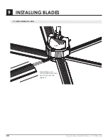
Страница 24: ...24 Canarm Hexa Lite 6LEC Series 10 24 Models 9 INSTALLING BLADES 9 1 Attach Blades to Hub Slide blade onto struts until blade holes and strut holes are aligned...

Страница 25: ...5 16 Flat Washer d 12 5 16 18 Nylock Nut ATTENTION Upon completion of the mechanical installation of the fan and before powering on spin the fan around multiple times by hand to ensure all brackets a...

Страница 26: ...tating fan blades Pour r duire le risque de blessure ne pas plier les crochets lame lors de l installation les crochets l quilibre entre les lames ou de nettoyer la ventilateur Ne pas ins rer d objets...

Страница 27: ...tip Assembly Install wingtip on end of blade after blade has been securely attached to the strut Using a Phillips head screwdriver fasten wingtip to blade using a 6 x 5 8 Flat Phil Screw Wingtip Hardw...

Страница 28: ...s voltage dips and frequency time deviation Canarm n est pas responsable des perturbations de tension en r f rence explicite aux interf rences magn tiques lectroniques EMI Les perturbations de tension...

Страница 29: ...ectrical Code ANSI NFPA 70 1999 and all local codes The procedures and techniques outlined in this manual are merely a guide for proper installation Code compliance is YOUR responsibility Failure to c...

Страница 30: ...propre Contactez Canarm au 1 613 342 5424 si vous avez des questions concernant l installation lectrique de ce ventilateur For use with manufacturer supplied variable frequency drive only Not for use...

Страница 31: ...tor wire slot on the top of the chassis allows the power wire to be ran through or affixed to the side of the extension bar then conveniently through the top plate of the chassis and directly in to th...

Страница 32: ...the motor is required NOTE Canarm suggests using a field supplied fused disconnect switch 1 Phase Voltage 230V 1Ph 3 Phase Voltage 230V 3ph 460V 3ph See Controller Data Sheet 6 Core Shielded Conducto...

Страница 33: ...iring to a Fire Alarm Panel If the installation of the fan is required to be wired to a fire alarm emergency shut off an external relay will have to be placed by a fire suppression specialist between...

Страница 34: ...tible with Canarm fans Is the input voltage correct Fix incorrect wiring Is the fan making any noise End of troubleshooting Yes Yes Yes No No No Check splices and wiring at the controller Is the Wirin...

Страница 35: ...s low at splice of the fan motor Under volt may be occurring a line reactor may need to be placed to reach correct voltage Vibration 8 Blinks Second Check all brackets and bolts Ensure bolts are torqu...

Страница 36: ...ing at the motor controller and from the controller to the supply b Do not run your controller and sensitive equipment on the same power line c Install properly sized EM RFI filter d Contact Customer...

Страница 37: ...T Risk of fire electric shock or injury to persons during cleaning and user maintenance Risque d incendie de choc lectrique ou de blessures lors du nettoyage et de l entretien par l utilisateur Discon...

Страница 38: ...38 Canarm Hexa Lite 6LEC Series 10 24 Models DATE MAINTENANCE PERFORMED REPLACEMENT PARTS REQUIRED 12 USER SERVICING INSTRUCTIONS Replacement Part List Maintenance Log PART NO DESCRIPTION...

Страница 39: ...Canarm Hexa Lite 6LEC Series 10 24 Models 39 NOTES...

Страница 40: ...LIM6LEC 0123_02 www canarm com PHONE 1 613 342 5424 FAX 1 800 263 4598 E Mail hvacsales canarm ca...

Отзывы: