Pg.
#4
Pg.
#9
1.
2.
6.
7.
A
INST
INST
ALLA
ALLA
TION
TION
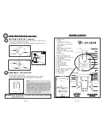
INSTALL MOUNTING BRACKET
- Install J-Hook through centre of outlet box and into the wooden joist.
- Mount “mounting bracket” to outlet box using outlet box screws.
ELECTRICAL HOOK UP
- There are several different wiring combinations that can be used in
controlling your ceiling fan to meet your specific requirements. Should
the following method not meet your requirements call or visit your
nearest Canarm distributor for a full list of fan accessories.
CAUTION
Green Wire - GROUND
Black Wire (Fan) - POWER
White Wire (Fan) - COMMON
Red or Blue Wire (Light Kit) - POWER
SEE SAFETY PRECAUTIONS ON
PG. #2 BEFORE WIRING
J-Hook
Mounting
Bracket
Outlet
Box
Wood Joist
Ceiling
J-Hook
Mounting
Bracket
Outlet Box
Wood Joist
Ceiling
Style #1
Style #2
MOUNTING BLADE BRACKETS
AND BLADES TO MOTOR
- Remove motor screws and lock
washers from motor.
- Insert a motor screw and lock
washer into blade bracket.
- Turn motor until hole spacing on
motor corresponds with the
holes in the blade bracket.
- Place fibre bracket gasket over
screw.
- Screw the motor screw into the
motor (two turns). Repeat
procedure for second screw.
- Tighten both screws down with
screw driver.
Motor Screw
Lock Washer
Fibre Bracket Gasket
LIGHT KITS (Optional in some fans)
DETACHABLE LIGHT KITS
- Remove light kit screws and
washers.
- Connect polarized connectors of
light kit to corresponding
connectors found in switch
housing.
WARNING: BE SURE TO
TURN OFF POWER
BEFORE INSTALLING
- Carefully tuck electrical wires
back into switch housing, align
light kit with switch housing and
secure with three light kit screws
and washers.
Motor
Red or Blue
Wires
Light Kit
Screws
Light Kit
Switch
Housing
White Wires
Lockwasher
NOTE:
All set screws must be checked and
retightened where necessary
,
before and after
installation.
WARNING: To Reduce The Risk Of Fire, Electric Shock, Or Personal
Injury, Mount To UL/CSA Listed Outlet Box Marked Acceptable for
Fan Support And Use Mounting Screws Provided With The Outlet Box.
Black or
Blue Wires
Fig. 2a
Fig. 2b
Fig. 7
Fig. 8
Outlet box Screws
(not provided)
Outlet box Screws
(not provided)


