Sep-07
OPERATION
1. After electrical connections are completed, energize the unit momentarily and ensure that the rotation of the
wheel is correct. Apply full power.
2. With the air systems in full operation and all ducts and access panels attached, measure current input to the
motor and ensure that it is less than the rated full load motor amperage.
3. Proper adjustment to the belt tension is critical for quiet efficient operation.
MAINTENANCE
Ens
ure
pow
er
s
u
pply
i
s d
i
sconn
e
ct
e
d and lock
e
d o
u
t p
ri
o
r
to p
er
fo
r
m
i
n
g
ma
i
nt
e
nanc
e
1. Inspect and tighten the wheel set screw after the first 50 to 100 hours of operation and periodically thereafter.
2. Follow the motor manufacturer’s instructions for motor lubrication. Remove any excess lubrication.
3. Check the Drives:
a.
Tighten set screws on sheaves, wheel and bearing locking collars.
b.
Check belt tension and alignment.
c.
Replace cracked or worn belts.
4. Check the wiring to be sure its secure and well insulated.
5. Blower bearings are pre-lubricated by the manufacturer. Generally, bearings should be lubricated at six to
twelve month intervals. The recommended lubricant is Shell Alvania #2 or S3. A small amount of grease should
be added slowly when the shaft is rotating. Note: Over greasing may cause damage to the bearing. Avoid
rupturing the bearing seal.
6. Inspect V-belts for wear and proper tension. If it is necessary to replace one belt on a multiple belt drive, replace
all the belts with a matched set. Do not use belt dressing.
7. Clean the blower wheel periodically. Material build up on the blades can cause wheel imbalance which may
result in wheel or bearing failure.
8. To reinstall replacement ball bearings, remove any burrs on the shaft with emery cloth or a fine file. Wipe shaft
with a clean cloth. Slide the bearing and housing on the shaft, position it and bolt pillow block securely to the
bearing support. Position the shaft to ensure the wheel properly fits to the inlet venturi. Alternatively tighten
each set screw with the proper hex head socket wrench until the wrench starts to spring.
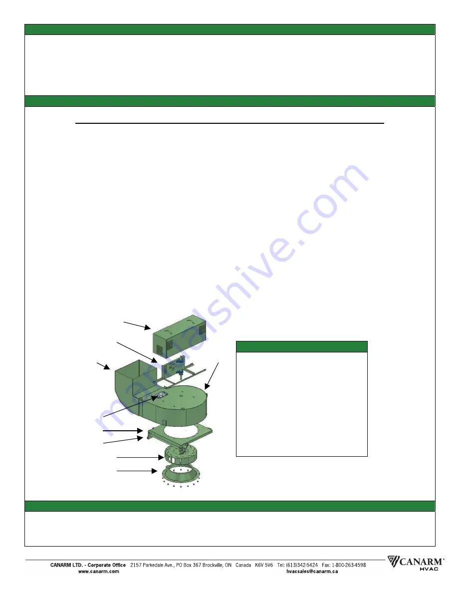
9. Should further service to the blower be necessary, refer to the exploded view illustration (see Figure 4).
PARTS LIST
1. DRIVE COVER ASSEMBLY
2. DRIVE FRAME ASSEMBLY
3. BLOWER HOUSING
4. LIFTING FRAME CAP
5. BAC
K
WARD INCLINED WHEEL
6. VENTURI
7. GREASE DRAIN
8. ACCESS DOOR
9. HINGE
10. GAS SPRING
F
igure
4
:
Explod
e
d v
ie
w
WARRANTY
This equipment is warrantied for a period of one year against manufacturing defects in material and workmanship when
operating under normal conditions. Liability is limited to the replacement of defective parts. Labour and transportation
costs are not included.
1
2
3
8
4
5
6
7
9/
10


