Pg. #8
Pg. #5
INST
INST
ALLA
ALLA
TION
TION
NOTE:
All set screws must be checked and
retightened where necessary, before and
after installation.
1
1
.
.
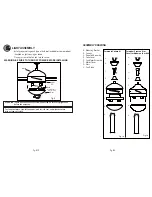
ATTACH THE FAN BLADES
- Attach the blades to the
fan motor assembly using
the screws, metal washer
and fibre washer. Slightly
turn the blade after
installation and repeat the
same step for the other
blades.
- Re-attach the cover to
the top housing.
ELECTRICAL HOOK-UP
4
4
.
.
Fig.2d
Fig.2c
Fig.2e
Metal Washer
Blade Bracket Screw
Blade
Blade Bracket
Screw
Screw
Fibre Washer
For model Preston III or
Cove II or Moderne IV or
CAUTION
SEE SAFETY PRECAUTIONS ON
PG. #2 BEFORE WIRING
Green Wire - GROUND
Black Wire (Fan) - POWER
White Wire (Fan) - COMMON
Red or Blue Wire (Light Kit) - POWER
- There are several different wiring combinations that can be used in
controlling your ceiling fan to meet your specific requirements. Should
the following method not meet your requirements call or visit your nearest
distributor for a full list of fan accessories.
After making the wire connections, ensure the wires should be spread
apart with the grounded conductor and the equipment-grounding
conductor on one side of the outlet box and the ungrounded conductor
on the other side of the outlet box.
Ensure the splices after being made should be turned upward and
pushed carefully up into the outlet box.
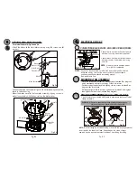
CONNECTING THE (GREEN) GROUND WIRE
- Connect ground wire from outlet box
to green wire from mounting bracket
and downrod using a
(not supplied).
NOTE
: Once ground wires are connected, carefully tuck wires and
into the
outlet box making sure that the wires are clear of the hemisphere and
downrod when positioned in mounting bracket (Downrod Mount Only).
- Connect ground wire from outlet box
to green wire from mounting bracket
using a
(not supplied).
DOWNROD MOUNT
FLUSH MOUNT
A
Fig. 5b
Fig. 5a
Marette
Marette
marette
marette
marette
B
B
- Remove the cover on
the top housing.
Mill
:
Fig. 2 c , 2 d and 2 e


