background image

EN-Rev IM-FDM-EU/1.7 Copyright © April 2019. Canadian Solar Inc.

4 | 

connector.

Do not 

allow children and unauthorized 

persons near the installation site or 
storage area of modules.

·  Do not install modules in strong wind.

·  If the disconnects and over current protective 

devices (OCPD) cannot be opened or the inverter 
cannot be powered down, cover the fronts of 
modules in the PV array with an opaque material 
to stop the production of electricity when installing 
or working on a module or wiring.

·  Use electrically insulated tools to reduce the risk of 

electric shock.

· 

Do not

 use or install broken modules.

·  Contact with module surfaces or frames may cause 

electric shock if the front or rear glass is broken.

·  Keep the junction box cover closed at all times.

· 

Do not 

connect or disconnect modules when 

current from the modules or an external source is 
present.

· 

Do not


disassemble a module or remove any 

  module part.

· 

Do not


artificially concentrate sunlight onto 


a module.  

·  The PV module does not contain any serviceable parts. 

Do not attempt to repair any part of the module.

2.1  INFORMATION PURSUANT TO ART. 33 

OF THE REACH REGULATION

Pursuant to Art. 33 of Regulation (EC) No 1907/2006 
of the European Parliament and of the Council of 18 
December 2006 concerning the Registration, Evalua-
tion, Authorisation and Restriction of Chemicals 
(REACH), establishing a European Chemicals Agency, 
amending Directive 1999/45/EC and repealing Coun-
cil Regulation (EEC) No 793/93 and Commission Re-
gulation (EC) No 1488/94 as well as Council Directive 
76/769/EEC and Commission Directives 91/155/EEC, 
93/67/EEC, 93/105/EC and 2000/21/EC (the “REACH 

Regulation”), we inform you that our solar modules 
contain a Substance of Very High Concern (“SVHC”) 
in a concentration above 0.1 % (weight by weight).

The coating of the ribbon of our solar modules 
contains lead (CAS no. 7439-92-1). Under normal or 
reasonably foreseeable conditions of use, exposure 
to the lead that is contained in our solar modules 
can be excluded. However, a release of, and expo-
sure to, lead can take place (i) when the different 
components of the solar modules are disassembled, 
in particular for recycling purposes, and (ii) in instan-

ces of fire.

Lead may damage fertility or the unborn child, 
causes damage to organs through prolonged or 
repeated exposure, is very toxic to aquatic life with 
long lasting effects, may cause cancer, is very toxic 
to aquatic life, and may cause harm to breast-fed 
children.

Therefore, recycling and all other types of compara-
ble disassembly of the solar modules have to be per-

formed by a qualified waste management company, 

in compliance with national and local waste manage-
ment regulations.

In the instance of fire, please keep away from the 
fire, and call the local fire brigade.

3.0  

MECHANICAL / ELECTRICAL 

SPECIFICATIONS

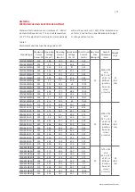
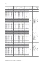
Module electrical ratings are measured under 
Standard Test Conditions (STC) of 1000 W/m2 
irradiance, with an AM1.5 spectrum, and a cell 
temperature of 25°C. Detailed electrical and 
mechanical characteristics of Canadian Solar Inc. 
crystalline silicon PV modules can be found in 
Annex A (Mechanical And Electrical Ratings). Main 
electrical characteristics under STC are also stated 
on each module label. Please refer to the datasheet 
or the product nameplate for the maximum system 
voltage.

Under certain conditions, a module may produce 
more current or voltage than its STC rated power. As 
a result, a module open-circuit voltage and short-
circuit current under STC should be multiplied by 
1.25 when determining component voltage ratings, 
conductor ampacities, overcurrent device ratings, 

Содержание CS3U-MS-FG

Страница 1: ...INSTALLATION MANUAL OF DYMOND MODULE For professional use only...

Страница 2: ...ICAL ELECTRICAL SPECIFICATIONS 4 0 UNPACKING AND STORAGE 5 0 MODULE INSTALLATION 5 1 MODULE WIRING 5 2 MODULE GROUNDING 6 0 MOUNTING INSTRUCTIONS 7 0 MAINTENANCE AMENDED EDITIONS AND DATES ANNEX A MEC...

Страница 3: ...c shall not be held responsible for damages of any kind including without limitation bodily harm injury or damage to property in connection with handling PV modules system installation or compliance o...

Страница 4: ...stance of Very High Concern SVHC in a concentration above 0 1 weight by weight The coating of the ribbon of our solar modules contains lead CAS no 7439 92 1 Under normal or reasonably foreseeable cond...

Страница 5: ...es under any circumstances Localized heavy loads may cause severe micro cracks at cell level which in turn may compromise module reliability and void Canadian Solar Inc s warranty Do not drop or place...

Страница 6: ...ng system supplier ENVIRONMENTAL CONDITIONS The module is intended for use in general open air climates as defined in IEC 60721 2 1 Classification of environmental conditions Part 2 1 Environmental co...

Страница 7: ...ar Permanent shading conditions can affect module service lifetime due to accelerated ageing of the encapsulation material and thermal stress on the bypass diodes RELIABLE VENTILATION Sufficient clear...

Страница 8: ...n North America and single conductor cable 2 5 16 mm 5 14 AWG 90 C wet rated in other areas i e TUV 2PfG1169 or EN50618 approved with proper insulation which is able to withstand the maximum possible...

Страница 9: ...ng torques should respectively be within 17 23 Nm 12 5 17 0 ft lb for M8x1 25 Grade 8 8 5 16 18 Grade B7 galvanized or A2 70 stainless steel coarse thread bolts depending on bolt class The yield stren...

Страница 10: ...not make modifications to any component of the PV module diode junction box plug connectors or others Regular maintenance is required to keep modules clear of snow bird droppings seeds pollen leaves b...

Страница 11: ...G 395 40 6 9 73 48 4 10 25 CS3U 400MS FG 400 40 8 9 81 48 6 10 33 CS3U 405MS FG 405 41 9 88 48 8 10 41 CS3U 410MS FG 410 41 2 9 96 49 10 49 CS3U 310P FG 310 37 2 8 34 44 7 8 88 30 2000 x 992 x 5 8 78...

Страница 12: ...33 5 9 56 40 1 9 97 CS3K 325P FG 325 33 7 9 65 40 3 10 05 CS6K 245P FG 245 30 0 8 17 37 1 8 74 15 1658 992 5 8 65 3 39 1 0 23 in without junction box and corner protector 23 50 7 lbs CS6K 250P FG 250...

Страница 13: ...77 5 39 1 0 23 in without junction box and corner protector 27 5 60 6 lbs CS6X 295P FG 295 36 0 8 19 44 5 8 76 CS6X 300P FG 300 36 1 8 30 44 6 8 87 CS6X 305P FG 305 36 3 8 41 44 8 8 97 CS6X 310P FG 3...

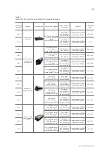
Страница 14: ...n and local climate Determination of the design loads is the responsibility of the racking suppliers and or professional engineers For detailed information please follow local structural code or conta...

Страница 15: ...mp length 100 mm four clamps A 380 20 mm see illustration A Downforce load 2400 Pa Uplift load 2400 Pa VDE CSA 2 C 2 Profi clamp wide 3 8 mm clamp length 200 mm four clamps A 380 20 mm see illustratio...

Страница 16: ...ngth 100 mm six clamps A 250 20 mm B 579 20 smm see illustration B Downforce load 5400 Pa Uplift load 2400 Pa VDE CSA 2 F 1 Akcome Metals Technology Suzhou Co Ltd AK EC DG End clamp AK MC DG Middle cl...

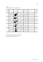
Страница 17: ...i clamp wide 3 8 mm clamp length 130 mm four clamps A 440 20 mm see illustration A Downforce load 2400 Pa Uplift load 2400 Pa VDE CSA 3 C 2 Profi clamp wide 3 8 mm clamp length 250 mm four clamps A 44...

Страница 18: ...mm B 684 20 mm see illustration B Downforce load 5400 Pa Uplift load 2400 Pa VDE CSA 3 F 1 Akcome Metals Technology Suzhou Co Ltd AK EC DG End clamp AK MC DG Middle clamp clamp length 130 mm four clam...

Страница 19: ...400 Pa VDE CSA 4 C 1 Xiamen Grace SolarTechnology co ltd GS IC Middle clamp GS EC End clamp clamp length 200 mm four clamps A 380 20 mm see illustration A Downforce load 5400 Pa Uplift load 2400 Pa VD...

Страница 20: ...tter GmbH Profi clamp wide 3 8 mm clamp length 250 mm four clamps A 440 20 mm see illustration A Downforce load 5400 Pa Uplift load 2400 Pa VDE CSA 5 C 1 Xiamen Grace SolarTechnology co ltd GS IC Midd...

Отзывы: