4.
TEST
THE
ELECTRICAL
CONDUCTORS
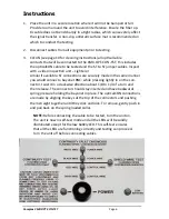
Connect
the
cable
to
be
tested
and
turn
the
unit
ON
via
the
power
switch.
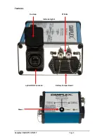
The
LEDs
and
the
diagnos c
infographic
on
the
top
of
the
unit
indicate
wire
status.
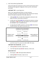
CONTINUITY TEST
–
overall
diagnos cs
NOTE:
If
your
op calCON
cable
does
not
contain
electrical
conductors,
the
electrical
con nuity
tests
will
fail.
This
does
NOT
indicate
failure
of
the
op cal
component
of
the
cable
under
test.
A
fl
ashing
BLUE
LED
on
the
le
of
the
infographic
indicates
that
the
copper
conductors
have
proper
con nuity.
A
con nuous/non
‐
fl
ashing
BLUE
LED
indicates
that
there
are
con nu
‐
ity
problems.
A
RED
LED
for
each
wire
indicates
which
wire(s)
failed.
See
CONTINUITY
FAULT
DIAGNOSIS
below.
As
required
by
the
SMPTE
standard,
a
con nuous
BLUE
LED
indicates
a
failed
shield
wire
test
which
means
there
is
an
overall
fail
status
of
the
cable.
See
SHIELD
WIRE
TEST
below.
CONTINUITY FAULT DIAGNOSIS
–
per
wire
A
fl
ashing
RED
LED
indicates
an
open
circuit.
A
non
‐
fl
ashing/con nuous
RED
LED
indicates
a
short
circuit.
SHIELD WIRE TEST
On
the
right
is
a
RED
LED
labeled
SHIELD
WIRE
TEST.
A
fl
ashing
RED
LED
indicates
an
open
circuit.
Camplex CMX
‐
OPT
‐
CON
‐
TST
Page
7


