Campbell Wind Monitor Series Скачать руководство пользователя страница 14

Wind Monitor Series 

7.


Select any other sensors you have, then finish the remaining 

Short Cut


steps to complete the program.  The remaining steps are outlined in 

Short 

Cut


Help

, which is accessed by clicking on 

Help | Contents |


Programming Steps

8.


If 

LoggerNet

PC400

RTDAQ

, or 

PC200W

 is running on your PC, and the 

PC to datalogger connection is active, you can click 

Finish

 in 

Short Cut


and you will be prompted to send the program just created to the 

datalogger. 

9.


If the sensor is connected to the datalogger, as shown in the wiring 

diagram in step 6, check the output of the sensor in the datalogger support 

software data display to make sure it is making reasonable measurements. 

5.  Overview 

Wind speed is measured with a helicoid-shaped, four-blade propeller.  Rotation 

of the propeller produces an AC sine wave signal with frequency proportional 

to wind speed. 

Vane position is transmitted by a 10 k

 potentiometer.  With a precision 

excitation voltage applied, the output voltage is proportional to wind direction. 

The R.M. Young Instruction Manual includes additional information on the 

operating principles, installation, and maintenance of the sensor. 

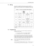
The wind monitors are manufactured by R.M. Young and cabled by Campbell 

Scientific for use with our dataloggers.  Lead lengths for the wind monitors are 

specified when the sensors are ordered.  TABLE 

5-1

 gives the recommended 

lead length for mounting the sensor at the top of the tripod/tower with a 

CM200-series crossarm. 

TABLE 5-1.  Recommended Lead Lengths 

CM106  CM110  CM115  CM120 

UT10 

UT20 

UT30 

13 ft 

13 ft 

19 ft 

24 ft 

13 ft 

24 ft 

34 ft 


Maximum cable length is 1000 feet. 


Do not use long lead lengths in electrically noisy 

environments. 

The wind monitor’s cable can terminate in: 


Pigtails that connect directly to a Campbell Scientific datalogger 

(option –PT). 


Connector that attaches to a prewired enclosure (option –PW).  Refer 

to 

www.campbellsci.com/prewired-enclosures


for more information. 


Connector that attaches to a CWS900 Wireless Sensor Interface 

(option –CWS).  The CWS900 allows the wind monitor to be used in 

a wireless sensor network.  Refer to 

www.campbellsci.com/cws900


for 

more information. 

NOTE 

CAUTION 

Содержание Wind Monitor Series

Страница 1: ...INSTRUCTION MANUAL Wind Monitor Series 05103 05103 45 05106 05108 05108 45 and 05305 Revision 12 15 C o p y r i g h t 1 9 8 4 2 0 1 5 C a m p b e l l S c i e n t i f i c I n c...

Страница 2: ......

Страница 3: ...ucts to CSI CSI will return such Products by surface carrier prepaid within the continental United States of America To all other locations CSI will return such Products best way CIP port of entry per...

Страница 4: ...g container Campbell Scientific s shipping address is CAMPBELL SCIENTIFIC INC RMA _____ 815 West 1800 North Logan Utah 84321 1784 For all returns the customer must fill out a Statement of Product Clea...

Страница 5: ...beginning work Wear a hardhat and eye protection and take other appropriate safety precautions while working on or around tripods and towers Do not climb tripods or towers at any time and prohibit cl...

Страница 6: ......

Страница 7: ...logger and Generate Wiring Diagram 3 5 Overview 6 6 Specifications 7 7 Installation 9 7 1 Siting 9 7 2 Assembly and Mounting 9 7 3 Wiring 11 7 4 Programming 11 7 4 1 Wind Speed 12 7 4 2 Wind Direction...

Страница 8: ...ion angles east of True North are subtracted from 0 to get True North C 2 C 3 Declination angles west of True North are added to 0 to get True North C 3 D 1 05103 potentiometer in a half bridge circui...

Страница 9: ...ellsci com old manuals or contact a Campbell Scientific application engineer for assistance 2 Precautions READ AND UNDERSTAND the Safety section at the front of this manual The wind monitor is a preci...

Страница 10: ...sarm to a tripod or tower 3 Orient the crossarm North South with the 17953 NU RAIL on the north end Appendix C Wind Direction Sensor Orientation p C 1 contains detailed information on determining true...

Страница 11: ...erminals The following procedure shows using Short Cut to program the sensor 1 Install Short Cut by clicking on the install file icon Get the install file from either www campbellsci com the ResourceD...

Страница 12: ...Wind Monitor Series 4 3 When Short Cut opens select New Program 4 Select the Datalogger Model and enter the Scan Interval default of 5 seconds is OK for most applications Click Next...

Страница 13: ...AQ Wind Speed Direction Sensor Click to move the selection to the Selected device window The wind speed defaults to meters second This can be changed by clicking the Wind Speed box and selecting one...

Страница 14: ...is proportional to wind direction The R M Young Instruction Manual includes additional information on the operating principles installation and maintenance of the sensor The wind monitors are manufact...

Страница 15: ...000 and CR9000 X TABLE 6 1 Wind Speed Specifications 05103 Wind Monitor 05103 45 Wind Monitor Alpine 05106 Wind Monitor MA 05108 Heavy Duty Wind Monitor 05108 45 Heavy Duty Wind Monitor Alpine 05305 W...

Страница 16: ...10 k linearity 0 25 life expectancy 50 million revolutions Power switched excitation voltage supplied by datalogger TABLE 6 3 Physical Specifications 05103 Wind Monitor 05103 45 Wind Monitor Alpine 05...

Страница 17: ...D A 12 inch long mounting pipe ships with the wind monitor for attaching the sensor to a CM200 series crossarm with the CM220 FIGURE 7 1 or 1049 NU RAIL fitting FIGURE 4 1 in QuickStart section The 05...

Страница 18: ...Wind Monitor Series 10 FIGURE 7 1 CM220 Right Angle Mounting Kit mounted to a crossarm FIGURE 7 2 The CM216 allows the wind monitor to mount atop a tripod CM220 CM200 Series Crossarm...

Страница 19: ...matically configured by the measurement instruction 7 4 Programming Short Cut is the best source for up to date datalogger programming code Programming code is needed when creating a program for a new...

Страница 20: ...x B where M multiplier x number of pulses per second Hertz B offset TABLE 7 2 lists the multipliers to obtain miles hour or meters second when the measurement instruction is configured to output Hz Th...

Страница 21: ...wind speed unit vector mean wind direction and Standard Deviation of the wind direction optional using the measured wind speed and direction samples 8 Sensor Maintenance Every month do a visual audio...

Страница 22: ...e green wires should vary between about 1 k to 11 k depending on vane position Resistance when the vane is in the 5 degree dead band should be about 1 M Symptom Incorrect wind direction 1 Verify that...

Страница 23: ...System Office of Research and Development Research Triangle Park NC 27711 EPA 1987 On Site Meteorological Program Guidance for Regulatory Modeling Applications EPA 450 4 87 013 Office of Air Quality...

Страница 24: ...Wind Monitor Series 16...

Страница 25: ...te of the file name used when saving the Short Cut program 2 Open CRBasic Editor 3 Click File Open Assuming the default paths were used when Short Cut was installed navigate to C CampbellSci SCWin fol...

Страница 26: ...Appendix A Importing Short Cut Code Into CRBasic Editor A 2...

Страница 27: ...bles and Units Public Batt_Volt Public WS_ms Public WindDir Units Batt_Volt Volts Units WS_ms meters second Units WindDir Degrees Define Data Tables DataTable Hour True 1 DataInterval 0 60 Min 10 Wind...

Страница 28: ...S_ms WindDir FP2 False 0 0 0 FieldNames WS_ms_S_WVT WindDir_D1_WVT WindDir_SD1_WVT EndTable Main Program BeginProg Main Scan Scan 5 Sec 1 0 Default Datalogger Battery Voltage measurement BattV Battery...

Страница 29: ...1 DataInterval 0 60 Min WindVector WS_ms WindDir False 0 0 FieldNames WS_ms_S_WVT WindDir_D1_WVT WindDir_SD1_WVT EndTable Main Program BeginProg Main Scan Scan 5 Sec Default Datalogger Battery Voltag...

Страница 30: ...Appendix B Example Programs B 4...

Страница 31: ...ative and are subtracted from 360 degrees to get True North as shown FIGURE C 2 0 and 360 are the same point on a compass For example the declination for Logan Utah is 11 78 East 11 August 2015 True N...

Страница 32: ...ndix C Wind Direction Sensor Orientation C 2 FIGURE C 1 Magnetic declination for the contiguous United States 2015 FIGURE C 2 Declination angles east of True North are subtracted from 0 to get True No...

Страница 33: ...Appendix C Wind Direction Sensor Orientation C 3 FIGURE C 3 Declination angles west of True North are added to 0 to get True North...

Страница 34: ...Appendix C Wind Direction Sensor Orientation C 4...

Страница 35: ...rement result is the ratio of the measured voltage to the excitation voltage Vs Vx This ratio is related to the resistance as shown below s t s x s R R R V V The maximum value that Rs will reach is Rf...

Страница 36: ...Appendix D Wind Direction Measurement Theory D 2...

Страница 37: ......

Страница 38: ...ua Apinag s nbr 2018 Perdizes CEP 01258 00 S o Paulo SP BRASIL www campbellsci com br vendas campbellsci com br Campbell Scientific Canada Corp 14532 131 Avenue NW Edmonton AB T5L 4X4 CANADA www campb...

Отзывы: