Campbell VS1 Скачать руководство пользователя страница 23

A-1

APPENDIX A.  CHANGING RAM OR PROM CHIPS IN THE CR10

The CR10 has two sockets for Random Access
Memory (RAM) and one socket for
Programmable Read Only Memory (PROM).
The standard CR10 has 64K of RAM, (a 32K
RAM chip in each socket).  Earlier CR10s had
16K of RAM (an 8K RAM chip in each socket).

A.1  DISASSEMBLING THE CR10

The sockets provided for RAM and PROM are
located on the CR10 CPU circuit card inside the
CR10 can.  To expose the RAM and PROM
sockets, remove the two Phillips head screws
from the end opposite the connectors.  Remove
the end cap.  The ends of two circuit cards and
the RF shield will be visible (see Figure A-1).
Now lay the CR10 on a flat surface, (i.e., a
table), and push on the RF shield with your
thumbs while grasping the can with your hands.
Remove the circuit cards from the can.  Orient
the cards with the connector on the left and with
the card that matches Figure A-2 up.  The
Central Processing Unit (CPU) is found at
location H-9 and the three slots for RAM and
PROM will be directly beneath it.

A.2  INSTALLING NEW RAM CHIPS IN

CR10S WITH 16K RAM

The two 8K RAM chips are found at locations C-
11 and C-14.  With a small flat screw driver
gently pry out the two 8K RAM chips at these
locations and replace them with the 32K RAM
chips provided in the memory upgrade.  The
new chips should be installed so the notched
end is towards the nearest card edge.  Before
pushing the chips into the socket make certain
that all the pins are correctly seated.  After
installing the 32K chips check for pins that may
be bent or not firmly seated in the socket.  If you
notice a bent pin, remove the chip, carefully
straighten it and repeat the installation
procedure.

A.2.1  CHANGING JUMPERS

There are six jumpers used to configure
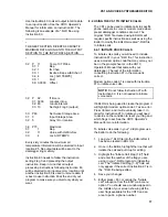
hardware for different RAM sizes.  Figure A-2
shows the jumper settings for different memory
configurations.  A pin or small screw driver tip
will work best for pulling these jumpers and
relocating them as shown in Figure A-2.

A.2.2  RAM TEST

Attach the CR10KD Keyboard/Display and apply
power to the CR10.  After the CR10 executes
the RAM/PROM self test, the number 96 should
be displayed in the window.  The number is the
sum of Kbytes in RAM (64) plus the number of
Kbytes in ROM (32).

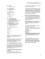
A.3  INSTALLING NEW PROM

The PROM chip is found at location C8 on the
CR10 CPU board, (see Figure A-2).  With a
small flat screw driver, gently pry out the PROM
chip and replace it with the new one.  The new
chip should be installed so that the notched end
is towards the nearest card edge.  Before
pushing the chip into the socket make certain
that all the pins are seating correctly.  After
installing the chip check for pins that may be
bent or not making contact.  If you notice a bent
pin, remove the chip, carefully straighten it and
repeat the installation procedure.

To make certain that the new chip is installed
correctly enter the CR10 *B mode, (Section 1.6
in the CR10 Operator's Manual), and advance
to the second window.  This window displays
the PROM signature.  The five digit number in
the window should match the PROM signature
given with the new PROM documentation.  If
the numbers are different disassemble the
CR10 and look for pins that are bent or not
firmly seated.

Содержание VS1

Страница 1: ...VS1 AND THE VOICE SYNTHESIZER EDITOR INSTRUCTION MANUAL 4 12 94 COPYRIGHT c 1994 CAMPBELL SCIENTIFIC INC...

Страница 2: ...f merchantability or fitness for a particular purpose CAMPBELL SCIENTIFIC INC is not liable for special indirect incidental or consequential damages Products may not be returned without prior authoriz...

Страница 3: ...alogger and the voice synthesis functions in the VS1 The VS1 can also be used as an originate modem at the datalogger site This allows the user to program the datalogger to call specific phone numbers...

Страница 4: ...RJ11C jack standard modular telephone jack Connection to telephone company provided COIN service Central Office ImplemeNted systems is prohibited Connection to party line service is subject to state...

Страница 5: ...ure 3 2 Connect the 14 AWG grounding wire provided with the VS1 to the grounding terminal GND on the VS1 Connect the other end to the CR10 ground G on the wiring panel If the enclosure has a grounded...

Страница 6: ...VS1 AND VOICE SYNTHESIZER EDITOR 4 FIGURE 3 2 Standard Telephone Jack Connection...

Страница 7: ...VS1 AND VOICE SYNTHESIZER EDITOR 5 FIGURE 3 3 Remote Site Connection...

Страница 8: ...o make occasional changes in their equipment operations or procedures If these changes might affect your service or the operation of your equipment the telephone company will give you notice in writin...

Страница 9: ...nthesizer Editor Pressing the symbol on the telephone keypad will cause the VS1 to repeat what is listed above Pressing the symbol will cause the VS1 to say goodbye and disconnect the phone For right...

Страница 10: ...to disconnect You can skip listening to the VS1 and go directly to the port or flag menu if you know what flag or port you wish to monitor or toggle You can go through the identical steps above with...

Страница 11: ...ghlight a different main menu option Press and hold Alt followed by the first letter of the main menu option Release both keys together Let s describe each individual main menu option and suboption st...

Страница 12: ...d with the CR10 See Section 8 4 in this manual for more details Again don t select any of the suboptions Now highlight the HELP main menu option 7 4 THE HELP MAIN MENU OPTION Notice there is only one...

Страница 13: ...left arrow keys 2 Use the Tab key to highlight DIRECTORIES If the DLD file is in a different drive or directory Use the up or down arrow key to highlight the drive and or directory To scroll quickly t...

Страница 14: ...e the window you should see two lines of text When you called the datalogger earlier it went through a message concerning the internal temperature of the datalogger as soon as the receiver was picked...

Страница 15: ...lar dot in the middle of the rectangle As you move the highlight bar down through the text area the rectangle on the bottom will move from left to right and the rectangle on the right hand side will m...

Страница 16: ...a mouse place the mouse cursor on the List option and click the left mouse button once For a keyboard press F2 to set up the editor to import words F2 puts the editor in the copy and paste mode for t...

Страница 17: ...t s run the changes Use the mouse or press Alt F to get into the file main menu options and select S ave to save your changes Exit out of the Editor and download the file to your datalogger Call the d...

Страница 18: ...y the pound button on the telephone Enter your specific security code followed by the pound button For example if my security code was 1234 I would enter 1234 from my touch tone phone After entering y...

Страница 19: ...ific instructions as well as using the Editor to modify the EDLOG created DLD file to initiate calls 8 4 1 INITIATE VOICE CALLS To initiate voice calls you will need to include Instruction 97 in your...

Страница 20: ...cts an alarm condition it will attempt to call the phone number everytime the alarm condition is met When the VS1 initiates a voice call it does not allow the user to listen to any of the initial mess...

Страница 21: ...nformation for the VS1 is added to the end of the DLD file This information can be checked to make sure it is accurate A copy of the VS1 information added to the end of EXMPL1 DLD follows The numbers...

Страница 22: ...used to initiate a voice call The 2 appears again in front of the phone number This last example uses the security code 1234 to allow access Notice the characters following the at the beginning of th...

Страница 23: ...ips check for pins that may be bent or not firmly seated in the socket If you notice a bent pin remove the chip carefully straighten it and repeat the installation procedure A 2 1 CHANGING JUMPERS The...

Страница 24: ...APPENIDX A CHANGING RAMOR PROM CHIPS IN THE CR10 A 2 FIGURE A 1 Disassembling CR10 FIGURE A 2 Jumper Settings for Different RAM Configurations...

Страница 25: ...Raised by a peripheral to put the CR10 in the telecommunications mode 4 RXD I Receive Data Serial data transmitted by a peripheral are received on pin 4 5 ME O Modem Enable Raised when the CR10 determ...

Страница 26: ...TY 26 EIGHTY 27 NINETY 28 HUNDRED 29 THOUSAND 30 MILLION 31 PRESS 32 POUND 33 DEW 34 HEAR 35 MENU 36 AGAIN 37 STAR 38 DISCONNECT 39 YOU 40 THE 41 HAVE 42 SELECTED 43 MONITOR 44 KEY 45 FOLLOWING 46 RET...

Страница 27: ...A 109 DATALOGGER 110 DAY 111 DEPTH 112 DEVIATION 113 DIRECTION 114 D O 115 DOWN 116 DRAW 117 EQUAL 118 ET 119 EVENT 120 EXTERNAL 121 EXCEEDS 122 FAHRENHEIT 123 FALL 124 FEET 125 FLOW 126 FROM 127 GALL...

Страница 28: ...ITY 190 VELOCITY 191 VOLTAGE 192 VOLTS 193 WARNING 194 WATER 195 WATTS 196 WEATHER 197 WELL 198 WIND STANDARD VS1 WORD LIST IN ALPHABETICAL ORDER 90 ACRE 36 AGAIN 91 AIR 92 ALARM 59 AND 93 ARE 94 AT 9...

Страница 29: ...2 HUMIDITY 28 HUNDRED 133 IN 134 INCHES 56 INPUT 135 INTERNAL 85 IS 44 KEY 136 KILO 77 KILOBYTES 137 LAST 138 LEVEL 139 LITER 57 LOCATIONS 50 LOW 141 MAXIMUM 78 MEMORY 35 MENU 142 MERCURY 72 MESSAGE 1...

Страница 30: ...SELECTED 69 SELECTION 130 SET 7 SEVEN 17 SEVENTEEN 25 SEVENTY 177 SIEMENS 75 SIGNATURE 178 SITE 6 SIX 16 SIXTEEN 24 SIXTY 179 SNOW 180 SOIL 181 SOLAR 182 SPEED 183 SQUARED 184 STAGE 185 STANDARD 37 S...

Страница 31: ...LOG TEMPC LOG TEMPF MODE 1 SCAN RATE 1 1 P10 1 1 2 P17 1 2 3 P37 1 2 2 1 8 3 3 4 P34 1 3 2 32 3 3 MODE 2 SCAN RATE 0 0000 MODE 3 MODE 10 1 28 2 64 3 0 0000 MODE 12 1 0 2 0 3 0000 56 57 53 52 4 88 89 1...

Страница 32: ...zed below For most applications the modem commands are issued automatically by the PC208 software The commands apply only when the modem is used as an originate modem which is not the primary use of t...

Страница 33: ...nications It has been tested and found to comply with the limits for a Class A computing device pursuant to Subpart J of Part 15 of FCC Rules which are designed to provide reasonable protection agains...

Страница 34: ...specify the reset state of the labell If the labell is reset this string will be spoken The format of the string will be required to end in a period No input location will be allowed in the string HE...

Страница 35: ...be used to create the voice strings To invoke this list press F2 or click on the LIST bar with the mouse The user can insert a word at the cursor position from the word list window by using a mouse o...

Страница 36: ...e entered in the following format The string must have a key word or phrase for example temp and an input memory location n where n is an input location from the CR10 Example THE TEMPERATURE IS 3 DEGR...

Отзывы: