


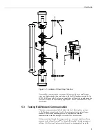


SC105 CS I/O to RS-232 Interface
4
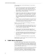
SC105 - SW Version 2.0
Main Menu:
Current Configuration
(1) CS I/O Port Configuration [Modem Enable]
(2) RS-232 Port Configuration [9600]
(3) Restore Factory Defaults
(4) Save and Exit
(5) Exit w/o Saving Settings
(9) Help
Enter Choice:
Figure 3-1. Set-up Menu
3.1
Set-up Menu Selections
1)
CS I/O Port Configuration
An SC105 may be activated either by the Modem Enable signal or by a
Synchronous Device (SDC) address (7, 8, 9, 10, or 11).
If PakBus Networking is being used, SDC address 7, 8, 10, or 11 should be
selected.
Addressed Print Device is a mode that allows output from the datalogger
when it executes the
P96
instruction.
2)
RS-232 Port Configuration
RS-232 baud rate, data bits, and parity are configured here, as well as the RS-
232 Auto Power Down (APD) Mode. The APD mode should be left enabled,
unless the attached RS-232 device requires power from the
RS-232 lines.
The DTR and RTS Mode setting allows control over how these two lines
behave.
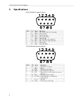
DTR is on pin 4 of the RS-232 connector; RTS is on pin 7.
‘PC/PDA mode’: DTR and RTS are both driven to 5 V.
‘Modem mode’: DTR will be driven to +5 V when the CS I/O interface is
active for Modem Enable, SDC Address 9, and Addressed
Print Device configurations. When the
CS I/O is inactive, DTR will be 0 V.
Additionally, there will be a ‘dead time’ after DTR is
dropped of 2 seconds when data coming in on the RS-232
will be ignored.


