


Section 2. Hardware Installation
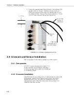
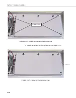
Screws
(4)
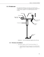
FIGURE 2.4-1. ET107 Sensor Arm Mounting
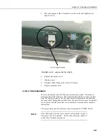
1) Remove the front lid and the protective connector cover from the back of
the ET enclosure by loosening the one Phillips screw at the bottom of the
cover.
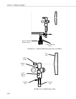
2) Place the sensor arm on top of the enclosure, lining up the four threaded
holes on the under side of the arm with the four holes in the top of the
enclosure. Attach the arm to the enclosure by inserting and tightening
four Phillips head screws. Adjust the position of the ET Enclosure so that
the crossarm is oriented along a due north to due south axis with the rain
gage and solar radiation sensor (pyranometer) on the south side for
northern latitudes and the reverse for southern latitudes.
2-9
Содержание ET107
Страница 8: ...ET107 Weather Station Table of Contents vi This is a blank page...
Страница 68: ...Section 3 ET Software 3 2 This is a blank page...
Страница 86: ...Section 4 Maintenance Troubleshooting and Schematics 4 18...
Страница 101: ...Appendix C Exploded Views C 1 Enclosure C 1...
Страница 102: ...Appendix C Exploded Views C 2 Crossarm C 2...
Страница 109: ......