DCSCOM Telephone Modem
2
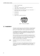
1. (input) +5V regulated supply
2. (input) Ground
3. (output) Ring: a logic high signifies a ring signal has been detected.
4. (output) Rx Data: serial data from modem
5. (input) Modem Enable: a logic high turns on 5V power to the modem. A
logic low shuts off 5V power to the modem.
6. No Connection
7. No Connection
8. No Connection
9. (input) Tx Data: serial data to the modem.
Figure 1 Connector Pin Diagram
2. Installation
The modem is designed to plug into a modern British Telecom modular telephone
socket. We do not recommend the connection of a telephone in parallel with the
modem as (by default) the modem will answer all incoming calls (see below).
If you intend to use the modem on a remote telephone line, we recommend that
you install lightning arrestors on the telephone line; note that the warranty on the
DCSCOM does not cover lightning damage. Please contact British Telecom or
Campbell Scientific for further details.
Once the modem has been connected to the telephone line, plug the special silver
25-way ‘D’ connector (marked ‘
DCSCOM INTERFACE
’) into the modem. Connect
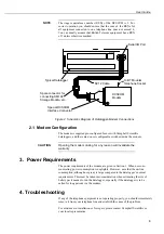
the interface to the datalogger’s serial I/O port using the 9-way SC12 ribbon cable
supplied. A connection diagram is shown in Figure 2. When the datalogger is
turned on, the modem will answer an incoming call.
The modem will not answer the telephone if the datalogger is not
powered up.
To check for correct operation, call the modem/datalogger from another telephone
using a modem connected to a PC running appropriate Campbell Scientific
datalogger support software. The DCSCOM detects the speed of incoming calls
automatically.
NOTE
Содержание DCSCOM
Страница 1: ...DCSCOM Telephone Modem User Guide Issued 1 3 99 Copyright 1999 Campbell Scientific Ltd...
Страница 2: ......
Страница 4: ......
Страница 6: ......
Страница 10: ......


