background image

Table 6-1: Command line variable definitions

ID

Name

Range

Description

Default

15

Power Supply Unit

(PSU) voltage level

shutdown

9 to 30

PSU input voltage level below which
the CS140 will enter low power mode.
This helps protect the batteries.

NOTE:
The CS140 shuts itself down via
hardware at about 8 VDC.

9

16

Enable alarm

0 or 1

0 = Alarm off

1 = Alarm on

0

17

Alarm high/low

0 or 1

0 = Alarm triggered by a luminance
higher than the alarm level

1 = Alarm triggered by a luminance
lower than the alarm level

0

18

Alarm level

0 to 45000 Luminance level, in cd/m

2

, that triggers

the alarm.

10000

1

Hood heater override needs to be set to 1 (off) when the hood heater has no power connected. This will save

power as the relay is not enabled at low temperatures in this mode.

2

If disabled the sensor does not check the validity of received data against the checksum sent. It is, however,

recommended that checksum checking is enabled to remove any chance of the CS140 being configured
incorrectly by accident.

6.4


Command


line


mode

The


command


line


interface


is


broken


down


into


three


major


commands.


These


are


GET

,


SET


and


POLL

.


The


GE

command


is


used


to


request


all


current


user


settable


values


from


the


CS140.


The


SET

commands


sets


user


settable


values


and


the


POLL

command


is


used


to


request


the


current


visibility


and/or


alarm


conditions


from


the


sensor.

The


CS140


can


be


configured


to


expect


any


commands


sent


to


it


to


include


a


valid


checksum.


For


simple


commands


such


as


GET

and


POLL

,


fixed


value


checksums


can


be


used.


For


more


complex


SET

commands


the


checksum


needs


to


be


calculated.


The


use


of


the


checksum


is


disabled


by


default.


Campbell


Scientific


recommends


enabling


the


checksum


functionality,


especially


when


long


cable


runs


are


used,


or


in


electronically


noisy


environments.


Example


C


code


of


the


CCITT


CRC


(p.


34)


provides


example


code


for


programmers


implementing


their


own


code.


For

CS140 Background Luminance Sensor

18

Содержание CS140

Страница 1: ...Revision 03 2022 Copyright 2013 2022 Campbell Scientific CSL I D 998...

Страница 2: ...under guarantee or not Please state the faults as clearly as possible and if the product is out of the guarantee period it should be accompanied by a purchase order Quotations for repairs can be give...

Страница 3: ...cell phones and aerials may also not be applicable according to your locality Some brackets shields and enclosure options including wiring are not sold as standard items in the European market in some...

Страница 4: ...beginning work Wear a hardhat and eye protection and take other appropriate safety precautions while working on or around tripods and towers Do not climb tripods or towers at any time and prohibit cl...

Страница 5: ...fications 5 3 6 Calibrator specifications 5 4 Installation 6 4 1 Location and orientation 6 4 2 Grounding 6 4 3 Mounting 7 4 4 Connectors 8 4 5 Wiring using supplied Campbell Scientific cables 9 4 6 M...

Страница 6: ...6 5 Menu system 23 7 Calibration 27 8 OS update 30 9 Maintenance 32 9 1 General 32 9 2 Cleaning 33 Appendix A Example C code of the CCITT CRC 34 Table of Contents ii...

Страница 7: ...sensor being damaged and data being lost NOTE Notes highlight useful information in the installation use and maintenance of this product These should be followed carefully in order to gain the maximu...

Страница 8: ...nted horizontally with the required 6 inclination built into the design Other angles are possible via the sensors mounting bracket A heated hood will prevent ice and snow from building up dew heaters...

Страница 9: ...rent consumption sampling continuously at 12 V 5 mA 7 mA 9 mA Current consumption sampling continuously with dew heater active at 12 V 90 mA 95 mA 100 mA Hood heater power supply Hood heater voltage A...

Страница 10: ...nput threshold voltage 0 2 V 0 2 V RS 485 output unloaded 5V RS 485 output load 50 2 V Maximum voltage at any terminal 7 V 7 V 3 4 Environmental specifications Temperature ranges Operating 25 to 60 C...

Страница 11: ...re range 0 to 40 C Calibration value 4 500 cd m2 Accuracy 6 Ingress protection IP52 Communication RS 232 38400 baud connecting the calibrator to the CS140 forces communications to RS 232 38400 baud an...

Страница 12: ...e or where measurements may be safety related Point the CS140 towards the desired luminance sources Ensure that only the light sources in which you are interested are within the sensor field of view T...

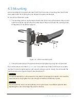
Страница 13: ...between the plate and brackets by tightening using the nuts provided The machine screws A and B in Figure 4 1 p 7 are used to level the CS140 Screw A is used to lock the CS140 at the right elevation...

Страница 14: ...r to the sensor The other connector provides power to the hood heater Figure 4 2 Connector layout Figure 4 3 p 8 shows the pin outs of the sockets viewed from outside Colours shown are the colours of...

Страница 15: ...R1000X using a suitable interconnecting cable such as the SC110 If another type of connection is required the D connector can be easily removed NOTE The maximum recommended cable length is 10 m Use a...

Страница 16: ...he baud rate and ID will return to those previously set Figure 4 5 Maintenance cable 4 7 Storage information The CS140 should be stored between 40 to 85 C in a dry place The optics should be protected...

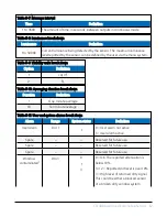
Страница 17: ...4 Message ID break down ID Definition 0 Basic format Contains only luminance and system information 1 Partial format Contains user alarm outputs 2 Full format Contains all system alarms codes Table 5...

Страница 18: ...ble 5 10 Averaging duration break down Duration Definition 1 One minute average 10 Ten minute average Table 5 11 User and system alarms break down Alarm Range System status Definition User Alarm 0 or...

Страница 19: ...2 Too high Over 70 C 3 Sensor fault No sensor detected or below 49 C Detector DC saturation level2 0 or 1 0 2 The amount of background light as seen by the detector hood 0 Within limits 1 Saturated T...

Страница 20: ...if the sun shines directly into the sensor 6 Interface methods 6 1 Command line menu 14 6 2 Configuring computer 15 6 3 Variable definitions 15 6 4 Command line mode 18 6 5 Menu system 23 6 1 Command...

Страница 21: ...ator to adjust the bits per second value in the port settings The CS140 can not communicate with the computer if the unit and port setting baud rates differ The CS140 should now be ready to accept com...

Страница 22: ...S140 luminance value 0 Candela per metres square cd m2 1 Foot lamberts fL 0 6 Message interval 1 to 3600 Interval in seconds between outputs in continuous mode This value has no effect if the polled m...

Страница 23: ...matically control the dew heater 1 Turn the dew heater off 0 12 Hood heater override1 0 or 1 0 Allow the CS140 to automatically control the hood heater 1 Turn the hood heater off 0 13 Dirty window com...

Страница 24: ...t is however recommended that checksum checking is enabled to remove any chance of the CS140 being configured incorrectly by accident 6 4 Command line mode The command line interface is broken down in...

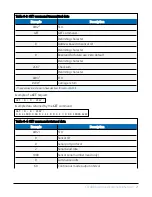
Страница 25: ...f the sensor The Set command is echoed back Example of a SET command and the echoed reply SET 0 0 0 2 0 0 10 1 2 1 1 0 0 0 1 9 5 0 0 10000 E52F 0 0 2 1000 0 10 1 2 1 1 0 0 0 1 9 5 0 0 10000 0146 Table...

Страница 26: ...difference is that the SETNC command does not commit the values set into flash memory This means that the next time the CS140 is power cycled it will revert back to its previous settings This command...

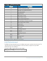
Страница 27: ...D1 Carriage return 1 These values are shown in hexadecimal format not ASCII Example of a GET request GET 0 0 2C67 Example data returned by the GET command GET 0 0 2C67 0 0 2 1000 0 60 0 2 1 1 0 0 0 1...

Страница 28: ...level Delimiting character 626C Checksum Delimiting character 0x041 EOX 0x0D1 Carriage return 0x0A Line feed 1 These values are shown in hexadecimal format not ASCII 6 4 4 Poll command The POLL comman...

Страница 29: ...e values are shown in hexadecimal format not ASCII 6 5 Menu system When connected to the CS140 the user can enter the menu system by typing open id in their terminal program then pressing the return k...

Страница 30: ...ou will be informed before any changes are made Type 1 to open the message menu containing settings relating to the CS140 outputs Menu 1 The message output menu CS140 MENU 1 ID 0 S N 1009 1 Toggle mes...

Страница 31: ...turn to main menu Option 3 gives the communications menu This is used to set baud rates and the mode of operation RS 232 RS 485 NOTE No change will take effect until you Exit and Save Menu 3 The commu...

Страница 32: ...ad errors Supply voltage Aux supply voltages 8 Get debug 9 Refresh 0 Return to main menu Alarm 0 0 0 0 0 0 0 9 0V 5V 5 0 Value 3100 0 No faults 0 28 0 22 7 100 100 00 33 00 30 00 4500 00 19 66 332 4 0...

Страница 33: ...ges are immediate but factory calibrations can be restored if needed using option 2 in the calibration menu 7 Calibration The CS140 can be checked and adjusted using the optional calibration device Th...

Страница 34: ...Refresh 0 Return to main menu Select option 1 to start the calibration At this point the calibration device and cable should be installed as shown in the following figures Connecting the calibrator sw...

Страница 35: ...turn after you type y Input the CS140CAL luminance value cd m2 4500 0 Is 4500 0 correct Y N Y Place the CS140CAL into the hood Ensure the CS140CAL is turned off then press any key H Starting dark leve...

Страница 36: ...Configuration Utility for full instructions on how to update the CS140 NOTE To use the Device Configuration Utility to carry out an OS change requires RS 232 communication However if a sensor is set...

Страница 37: ...Figure 8 1 CS140 Device Configuration Utility OS download instructions CS140 Background Luminance Sensor 31...

Страница 38: ...0 is a robust weather resistant instrument and there is no need for routine maintenance other than cleaning The instrument performance is monitored and any potential problems are covered by error mess...

Страница 39: ...and high dependency on the instrument output CAUTION If the window requires cleaning it is very important that only a proper lens cloth or lens tissue is used The use of inappropriate materials to cle...

Страница 40: ...self Creates a CCITT CRC16 checksum seeded with 0x0000 XModem style using a fast non table based algorithm Pass in the data to convert into a CRC in the form of a NULL terminated character array a str...

Страница 41: ...nfo campbellsci fr www campbellsci fr Germany Location Phone Email Website Bremen Germany 49 0 421 460974 0 info campbellsci de www campbellsci de India Location Phone Email Website New Delhi DL India...

Отзывы: