CS120A and CS125 Visibility and Present Weather Sensors
18
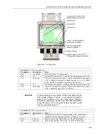
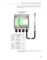
Figure 8-1. Connections
Connector A -
Five way connector
Pin number
Description
Notes
Pin 1
+ve supply
Main electve supply input
Pin 2
0V
Auxiliary Electronics 0V. Common with the main electronics 0V.
Pin 3
Hood low
This is for the hood heater power supply. If the hood heater supply
is DC it should be the negative connection and if it is AC it should
be the ‘neutral’ or ‘ground’ connection if there is one.
Pin 4
0V
Auxiliary Electronics 0V. Common with the main electronics 0V.
Pin 5
Hood high
This is for the hood heater power supply. If the hood heater supply
is DC it should be the positive connection.
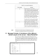
To avoid damage to noise filters on the hood heater inputs
if the heater voltage is DC the –ve connection should be
made to pin 3 and the +ve to pin 5. If the heater voltage is
AC with a ground or neutral wire then this should be
connected to pin 3. Pin 3 should not be more than 5 volts
from the main electronics 0V.
Connector B -
Three way connector
Pin number
Description
Notes
Pin 1
0V
0V connection for serial communications. This connection is
common with the main electronics 0V (Connector A, pin 2).
Pin 2
Receive
RS-232 receive line, RXD, B/D+ for RS-485 half duplex
Pin 3
Transmit
RS-232 transmit line, TXD, A/D
−
for RS-485 half duplex
CAUTION
Содержание CS120A
Страница 69: ...A 1 Appendix A CS120A CS125 block diagram...

