AM32 MULTIPLEXER
9
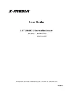
5.2 DIFFERENTIAL MEASUREMENTS
Sensor to Multiplexer wiring
- One differential
analog signal can be connected to each AM32
input channel for measurement.
Multiplexer to Datalogger wiring
- Signal lines
from the COM terminals are connected to a
differential analog input. Up to 32 differential
measurements can be made using one
differential datalogger channel.
FIGURE 5-2. Differential measurement.
5.3 HALF BRIDGE MEASUREMENTS
5.3.1 HALF BRIDGE MEASUREMENT WITH
COMPLETION RESISTOR AT DATALOGGER
Sensor to Multiplexer wiring - A half bridge
measurement can be made by connecting the
sensor resistance to an AM32 input channel.
Multiplexer to Datalogger wiring - Signal lines
from the multiplexer COM terminals are input to
an Excitation channel and a single-ended input.
A precision completion-resistor ties the analog
input channel to analog ground in the CR10(X)
or to datalogger ground in the 21X or CR7.
FIGURE 5-3. Half Bridge measurement with
resistor at the datalogger.
5.4 MIXED SENSOR TYPES
In applications where sensors types are mixed,
multiple hook-up configurations and
programming sequences are possible.
Section 7.3 contains an example of multiplexing
soil moisture blocks and thermocouples. If you
need assistance in multiplexing markedly
different sensor types, please contact Campbell
Scientific for support.
6.0 THERMOCOUPLE WIRING AND
MEASUREMENT CONSIDERATIONS
This section contains considerations for
multiplexing thermocouple measurements. The
Measurement Section of your datalogger
manual contains a thorough discussion of
thermocouple measurement and error analysis;
these topics will not be covered here.
6.1 REFERENCE JUNCTIONS
Thermocouple measurements must always be
referenced to a known temperature. As shown
in Figure 6-1 and 6-2, two configurations are
possible, reference at the datalogger or
reference at the AM32. If the multiplexer is
enclosed in an AM-ENCT, the recommended
reference junction location is at the multiplexer.
DATALOGGER REFERENCE
- The 21X and
the CR7 723-T (Analog Input card with RTD)
have built-in temperature references. For the
CR10(X), the 10TCRT Thermocouple
Reference may be purchased and installed on
the wiring panel between the two analog input
terminal strips.
A reference temperature sensor at the
datalogger should be insulated to minimize
thermal gradients. When using the 21X, the
terminal strip cover, supplied with datalogger,
should be in place. When using the CR7, its
cover-plate should be attached. When using
the CR10(X), the user may insulate the
datalogger.
When the reference junction is located at the
datalogger, the signal wires between the
datalogger and the AM32 must be of the same
wire type as the thermocouple (Figure 6-1). The
21X and CR7 have reference temperature
sensors installed under differential input
Содержание AM32
Страница 27: ...This is a blank page ...