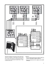


35
The outputs A, B, C and D may be either short or open-cir-
cuited. They are electrically insulated from each other and
from all other circuits (floating).
Y2
2 mA
Y2
1 mA
15 V
Y2
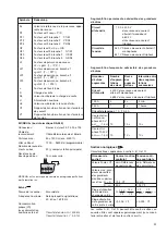
Analogue outputs
For the outputs A, B, C and D:
Output
Impressed
Impressed
variable Y
DC current
DC voltage
Full scale Y2
see “Ordering
see “Ordering
information”
information”
Limits of output
signal for input
overload
and/or
R = 0 1.25 · Y2
40 mA
R
→ ∞
30 V
1.25 Y2
Rated useful
range of output
0
≤
≤
≤
≤
∞
load
AC component
of output signal
≤
0.005 · Y2
≤
0.005 · Y2
(peak-to-peak)
MODBUS
®
(Bus interface RS-485)
Terminals:
Screw terminals, terminals 23, 24,
25 and 26
Connecting cable:
Screened twisted pairs
Max. distance:
Approx. 1200 m (approx. 4000 ft.)
Baudrate:
1200 … 9600 Bd (programmable)
Number of bus station: 32 (including master)
Dummy load:
Not required
25
24
26
23
GND
–
+
7.5 V
Y2
Symbols
Meaning
MODBUS
®
is a registered trademark of Schneider Automation Inc.
Input
Waveform:
Sinusoïdal
Rated frequency:
Acc. to type label
50, 60 or 16 2/3 Hz
Own consumption [VA]
(with external
power supply):
Voltage circuit: U
2
/ 400 k
Ω
Current circuit:
≤
I
2
· 0,01
Ω
PF
Active power factor cos
ϕ
= P/S
PF1
Active power factor phase 1 P1/S1
PF2
Active power factor phase 2 P2/S2
PF3
Active power factor phase 3 P3/S3
QF
Reactive power factor sin
ϕ
= Q/S
QF1
Reactive power factor phase 1 Q1/S1
QF2
Reactive power factor phase 2 Q2/S2
QF3
Reactive power factor phase 3 Q3/S3
LF
Power factor of the system
LF = sgnQ
·
(1 –
PF
)
LF1
Power factor phase 1
sgnQ1
·
(1 –
PF1
)
LF2
Power factor phase 2
sgnQ2
·
(1 –
PF2
)
LF3
Power factor phase 3
sgnQ3
·
(1 –
PF3
)
c
Factor for the intrinsic error
R
Output load
Rn
Rated burden
H
Power supply
Hn
Rated value of the power supply
CT
c.t. ratio
VT
v.t. ratio
Continuous thermal ratings of inputs
Current circuit
10 A 400 V
single-phase AC system
693 V
three-phase system
Voltage circuit
480 V single-phase AC system
831 V three-phase system
Short-time thermal rating of inputs
Input
Number
Duration Interval
variable
of
of
between two
inputs
overload overloads
Current circuit
400 V single-phase AC system
693 V three-phase system
100 A
5
3 s
5 min.
250 A
1
1 s
1 hour
Voltage circuit
1 A, 2 A, 5 A
Single-phase
AC system
600 V
H
intern
: 1.5 Ur
10
10 s
10 s
Three-phase
system
1040 V
H
intern
: 1.5 Ur
10
10 s
10 s
Содержание SINEAX DME 440
Страница 2: ...2 ...