background image

31

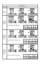
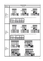
Connect the voltage according to the following table for current measurement in L2 or L3:

Current

Terminals

2

11

transformer

L2

1

3

L2

 N

L3

1

3

L3

 N

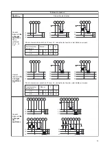
Connect the voltage according to the following table for current measurement in L2 or L3:

Current

Terminals

5

8

transformer

L2

1

3

L3

L1

L3

1

3

L1

L2

Measuring inputs

System /

application

Terminals

3-wire

3-phase

asymmetric
load

4-wire

3-phase

symmetric
load

I: L1

3-wire

3-phase

symmetric
load

Phase-shift
U: L2 – L3
I: L1

L1
L2
L3

k

l

K

L

k

l

K

L

x

x

x

u

u

u

X

X

X

U

U

U

5

1

8

2

3

7

9

L1
L2
L3

u

U

v

V

v

V

u

U

k

l

K

L

k

l

K

L

5

1

8

2

3

7

9

L1
L2
L3

5

1

8

2

3

7

9

L1
L2
L3

k

l

K

L

k

l

K

L

5

1

8

2

3

7

9

L1

N

11

3

1

2

L2
L3

L1

N

k

l

K

L

2 11

3

1

L2
L3

L1

v

V

u

U

k

l

K

L

2 11

3

1

N

L2
L3

L1

8

3

1

5

L2
L3

L1

k

l

K

L

5

8

3

1

L2
L3

L1

v

V

u

U

k

l

K

L

5

8

3

1

L2
L3

Содержание SINEAX DME 440

Страница 1: ...35 35 e mail info camillebauer com http www camillebauer com Betriebsanleitung Programmierbarer Multi Messumformer SINEAX DME 440 Mode d emploi Convertisseur de mesure multiple programmable SINEAX DME 440 Operating Instructions Programmable multi transducer SINEAX DME 440 DME 440 1 B d f e 127 127 02 11 05 ...

Страница 2: ...2 ...

Страница 3: ...rating Instructions indicate safety precautions which must be strictly observed Betriebsanleitung Programmierbarer Multi Messumformer SINEAX DME 440 Seite 4 Mode d emploi Convertisseur de mesure multiple programmable SINEAX DME 440 Page 16 Operating Instructions Programmable multi transducer SINEAX DME 440 Page 28 Geräte dürfen nur fachgerecht entsorgt werden Les appareils ne peuvent être éliminés...

Страница 4: ...hnittstelle die Geräteadresse die Baudrate sowie eine eventuelle Verlängerung der im MODBUS Protokoll defi nierten Telegrammpause falls der Master zu langsam ist definiert werden kann Programmieren lassen sich um die wichtigsten Parameter zu nennen alle üblichen Anschlussarten die Messgrössen die Bemessungswerte der Eingangsgrössen das Übertra gungsverhalten für jede Ausgangsgrösse und die Art der i...

Страница 5: ...tige Leitungen mit 2 2 5 mm2 Leitungsquerschnitt Unbedingt sicher stellen dass die Leitungen beim Anschliessen spannungsfrei sind Anschlussleitungen nach Tabelle anschliessen 1 2 3 2 4 1 1 1 5 165 22 21 20 19 18 17 16 15 8 7 6 5 4 3 2 1 26 25 24 23 14 13 11 9 GND A B C D Tx Rx UL2 UL1 UL1 UL3 IL1 IL2 IL3 N RS 232 Funktion Anschluss Messeingang Wechselstrom IL1 1 3 IL2 4 6 IL3 7 9 Wechselspannung U...

Страница 6: ...ber L2 bzw L3 Spannungsanschluss nach folgender Tabelle vornehmen Bei Strommessung über L2 bzw L3 Spannungsanschluss nach folgender Tabelle vornehmen L1 N k l K L 2 11 3 1 L1 N v V u U k l K L 2 11 3 1 L1 2 3 1 L1 k l K L 8 2 3 1 L1 v V u U k l K L 8 2 3 1 8 L2 L3 L2 L3 L2 L3 Dreileiter Drehstromnetz gleichbelastet Kunst schaltung U L3 L1 I L1 Bei Strommessung über L2 bzw L3 Spannungsanschluss nac...

Страница 7: ...emmenbelegung Dreileiter Drehstromnetz ungleich belastet Vierleiter Drehstromnetz gleichbelastet I L1 Dreileiter Drehstromnetz gleichbelastet Kunst Schaltung U L2 L3 I L1 L1 L2 L3 k l K L k l K L x x x u u u X X X U U U 5 1 8 2 3 7 9 L1 L2 L3 u U v V v V u U k l K L k l K L 5 1 8 2 3 7 9 L1 L2 L3 5 1 8 2 3 7 9 L1 L2 L3 k l K L k l K L 5 1 8 2 3 7 9 L1 N 11 3 1 2 L2 L3 L1 N k l K L 2 11 3 1 L2 L3 L...

Страница 8: ...die Einkopplung von Störungen vermindert Der Schirm ist zu erden An den Bus lassen sich bis zu 32 Teilnehmer inklusive Master anschliessen Grundsätzlich ist der Anschluss von Geräten aller Hersteller erlaubt welche sich an das Stan dard MODBUS Protokoll halten Geräte ohne galvanisch getrennte Bus Schnittstelle dürfen nicht an den Schirm angeschlossen werden Die optimale Konfiguration für den Bus is...

Страница 9: ...Din Data Out A Dout Data Out B Data In A Data in B Handshake Out A Handshake Out B Handshake In A Handshake In B PC 5 1 6 2 7 3 8 4 9 GND TxD RxD DTR DSR RTS CTS 5 3 2 4 6 7 8 Interface 86201 von W T Bild 8 Bild 8 zeigt wie der Anschluss der Messumformer DME440andenMODBUSerfolgenkann DieRealisationder RS 485 Schnittstelle kann mit einer in den PC eingebauten Schnittstellen Karte oder mit einem Kon...

Страница 10: ...ST Einstellzeit für BS ϕ Phasenverschiebungswinkel zwischen Strom und Spannung F Frequenz der Eingangsgrösse Fn Nennwert der Frequenz P Wirkleistung des Netzes P P1 P2 P3 P1 Wirkleistung Strang 1 Aussenleiter L1 und Sternpunkt N P2 Wirkleistung Strang 2 Aussenleiter L2 und Sternpunkt N P3 Wirkleistung Strang 3 Aussenleiter L3 und Sternpunkt N Q Blindleistung des Netzes Q Q1 Q2 Q3 Q1 Blindleistung ...

Страница 11: ...5 und 26 Anschlussleitung Verdrillte Zweidrahtleitung mit Abschirmung Max Distanz Ca 1200 m ca 4000 ft Baudrate 1200 9600 Bd programmierbar Anzahl Busteilnehmer 32 inklusive Master Busabschluss widerstände Nicht erforderlich 25 24 26 23 GND MODBUS ist eine eingetragene Handelsmarke von Schneider Automation Inc Zulässige kurzzeitig überhöhte Eingangsgrössen Überhöhte Anzahl Dauer Zeitraum Eingangs ...

Страница 12: ...U1 24 60 V AC int 24 60 V Self powered by U1 85 230 V AC int 85 230 V Programmier Anschluss am Messumformer Schnittstelle RS 232 C DSUB Buchse 9 polig Genauigkeitsklasse Bezugswert ist der Endwert Y2 Messgrösse Bedingung Genauigkeits klasse 0 5 X2 Sr 1 5 0 25 c 0 3 X2 Sr 0 5 0 5 c 0 167 X2 Sr 0 5 0 25 c 0 1 X2 Sr 0 167 0 5 c 0 5Sr S 1 5 Sr 0 25 c X2 X0 2 0 5Sr S 1 5 Sr 0 5 c 1 X2 X0 2 0 5Sr S 1 5 ...

Страница 13: ...bzw des adressierten Gerätes bei RS 485 Einfache Änderung der Eingangs und Busparameter mit übersichtlicher Darstellung Bild 12 Parameterübersicht Übertragen geänderter oder neuer Programmierdaten in den angeschlossenen adressierten Umformer Möglichkeit zur Archivierung von Programmier Dateien Passwortschutz für auswählbare Funktionen welche Messumformer Daten ändern können Programmierung aller üb...

Страница 14: ... Rx 26 RS485 MODBUS 1 2 3 4 000 100V 2 5A 16 8 kV 100V 2500A 2 5A 50Hz P1 85MW 85MW 20mA U12 0kV 18 5kV 0mA 20mA I3 F 49Hz 20mA 9600 Baud 0A 3000A 0mA 20mA 51Hz 20mA R L P Q Q P 0 25 c 0 25 c 0 15 0 03 c G C 20mA 0 25 c 15 16 A 17 18 B 19 20 C 21 22 D 23 Tx Rx 25 GND 24 Tx Rx 26 RS485 MODBUS 1 2 3 4 000 100V 2 5A 16 8 kV 100V 2500A 2 5A 50Hz P1 85MW 85MW 20mA U12 0kV 18 5kV 0mA 20mA I3 F 49Hz 20mA...

Страница 15: ...estigkeit in unserem Werk oder durch eine unserer Servicestellen zugelassen Beim Öffnen der Abdeckung können spannungsfüh rende Teile freigelegt werden Ein Abgleich eine Wartung oder eine Reparatur am geöffneten Gerät unter Spannung darf nur durch eine Fachkraft vorgenommen werden die mit den damit verbundenen Gefahren vertraut ist Kondensatoren im Gerät können noch geladen sein selbst wenn das Ge...

Страница 16: ...est important qu il soit possiblededéfiniràtraversl interfacel adressedel appareil le nombre de Baud et un éventuel prolongement de la pause entre les télégrammes définie dans le protocole MODBUS pour les cas d un support Master trop lent Voici un aperçu des possibilités de programmation les plus importantes tous les systèmes de raccordement usuels les grandeurs de mesure les valeurs des grandeurs d...

Страница 17: ...s conducteurs rigides de 4 mm2 ou des conducteurs souples de 2 2 5 mm2 de section Lors du raccordement des câbles se rassurer impérativement que toutes les lignes soient hors tension Raccorder les fils de connexion selon les indications du tableau 1 2 3 2 4 1 1 1 5 165 22 21 20 19 18 17 16 15 8 7 6 5 4 3 2 1 26 25 24 23 14 13 11 9 GND A B C D Tx Rx UL2 UL1 UL1 UL3 IL1 IL2 IL3 N RS 232 Fonction Conn...

Страница 18: ...L2 resp L3 connecter les tensions selon tableau ci après Pour la mesure du courant en L2 resp L3 connecter les tensions selon tableau ci après L1 N k l K L 2 11 3 1 L1 N v V u U k l K L 2 11 3 1 L1 2 3 1 L1 k l K L 8 2 3 1 L1 v V u U k l K L 8 2 3 1 8 L2 L3 L2 L3 L2 L3 Courant triphasé 3 fils à charges équilibrées Phase artificielle U L3 L1 I L1 Pour la mesure du courant en L2 resp L3 connecter le...

Страница 19: ...isposition des bornes Courant triphasé 3 fils à charges dés équilibrées Courant triphasé 4 fils à charges équilibrées I L1 Courant triphasé 3 fils à charges équilibrées Phase artificielle U L2 L3 I L1 L1 L2 L3 k l K L k l K L x x x u u u X X X U U U 5 1 8 2 3 7 9 L1 L2 L3 u U v V v V u U k l K L k l K L 5 1 8 2 3 7 9 L1 L2 L3 5 1 8 2 3 7 9 L1 L2 L3 k l K L k l K L 5 1 8 2 3 7 9 L1 N 11 3 1 2 L2 L3...

Страница 20: ...lindage doit être mis à terre Le bus permet le raccordement de jusqu à 32 appareils y compris le PC pilote Master Il est possible de raccorder tous les appareils de fabricants qui respectent le protocole standard MODBUS Les appareils non galvaniquement séparées ne doivent pas être connectés au blindage La meilleure configuration du bus est l interconnexion se lon daisy chain donc une structure en l...

Страница 21: ...5 Signal GND Sortie de données A Sortie de données B Entrée de données A Entrée de données B Message de colloque sortie A Message de colloque sortie B Message de colloque entrée A Message de colloque entrée B PC 5 1 6 2 7 3 8 4 9 GND TxD RxD DTR DSR RTS CTS 5 3 2 4 6 7 8 Interface 86201 de W T GND Din Dout Fig 8 Fig 8montrecommentraccorderleconvertisseurdemesure DME 440 au MODBUS La réalisation de...

Страница 22: ...tion de mesure bilame IBT Temps de réponse de IB BS Fonction d aiguille entraînée pour la mesure de la valeur effective IB BST Temps de réponse de BS ϕ Angle de déphasage entre cour et tension F Fréquence de la grandeur d entrée Fn Valeur nominale de fréquence P Puissance active du réseau P P1 P2 P3 P1 Puissance active branche 1 phase L1 et point neutre N P2 Puissance active branche 2 phase L2 et ...

Страница 23: ...o phasé 600 V à Hinterne 1 5 Ur 10 10 s 10 s Courant tri phasé 1040 V à Hinterne 1 5 Ur 10 10 s 10 s MODBUS est une marque de commerce enregistrée par Schnei der Automation Inc 25 24 26 23 GND Symbole Bedeutung Entrée Forme de la courbe Sinusoïdale Fréquence nominale Selon plaquette signalétique 50 60 ou 16 2 3 Hz Consommation propre VA avec alimentation auxiliaire externe Circuit de tension U2 40...

Страница 24: ...la plage de réponse X0 Y0 X2 Y2 Y X Valeurs limites de la plage de réponse X0 Y0 X2 Y2 X1 Y1 Fig 11 Exemple des possibilités de réglage avec une ligne brisée Fig 10 Exemple des possibili tés de réglage avec une ligne linéaire Effets et grandeurs d influence Selon EN 60 688 Sécurité électrique Classe de protection II Protection IP 40 boîtier IP 20 bornes de raccordement Degré d encrassement 2 Catégo...

Страница 25: ...o de commande 980 179 L interface RS 485 peut être utilisée soit avec une carte d interface interne du PC soit avec un convertisseur externe RS 232C RS 485 Le logiciel comporte une structure de menus faciles à utiliser et dont les fonctions et caractéristiques principales sont énumérées ci après Sélection et affichage de la programmation du con vertisseur raccordé resp de l appareil adressé par RS ...

Страница 26: ...plaquette sig nalétique voir Fig 15 et 16 Toute intervention dans l appareil entraîne l extinction de la clause de garantie 15 16 A 17 18 B 19 20 C 21 22 D 23 Tx Rx 25 GND 24 Tx Rx 26 RS485 MODBUS 1 2 3 4 000 100V 2 5A 16 8 kV 100V 2500A 2 5A 50Hz P1 85MW 85MW 20mA U12 0kV 18 5kV 0mA 20mA I3 F 49Hz 20mA 9600 Baud 0A 3000A 0mA 20mA 51Hz 20mA R L P Q Q P 0 25 c 0 25 c 0 15 0 03 c G C 20mA 0 25 c Fig...

Страница 27: ... 7 8 9 11 13 14 15 16 17 18 19 20 21 22 23 24 25 26 150 123 4 87 5 165 6 5 Ø 4 5 12 19 181 Fig 19 SINEAX DME en boîtier T24 avec languettes extraites pour montage mural direct Signification des symboles figurant sur l appareil Les symboles figurant sur l appareil signifient Avertit l utilisateur d un danger Attention voir la documentation Appareil de classe de protection II double isolation 13 Admissi...

Страница 28: ...configure the device address the Baud rate and possibly increasing the telegram waiting time if the master is too slow defined in the MODBUS protocol The usual methods of connection the types of measured variables their ratings the transfer characteristic for each output and the type of internal energy meters are the main parameters that can be programmed The ancillary functions include a power syst...

Страница 29: ...ors are designed as screw terminals They are suited for single wire leads of 4 mm2 or multiple wire leads of 2 2 5 mm2 cross section Make sure that the cables are not live when making the connections Connect the leads according to the table 1 2 3 2 4 1 1 1 5 165 22 21 20 19 18 17 16 15 8 7 6 5 4 3 2 1 26 25 24 23 14 13 11 9 GND A B C D Tx Rx UL2 UL1 UL1 UL3 IL1 IL2 IL3 N RS 232 Function Connect Me...

Страница 30: ...lowing table for current measurement in L2 or L3 Connect the voltage according to the following table for current measurement in L2 or L3 L1 N k l K L 2 11 3 1 L1 N v V u U k l K L 2 11 3 1 L1 2 3 1 L1 k l K L 8 2 3 1 L1 v V u U k l K L 8 2 3 1 8 L2 L3 L2 L3 L2 L3 3 wire 3 phase symmetric load Phase shift U L3 L1 I L1 Connect the voltage according to the following table for current measurement in ...

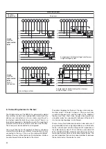
Страница 31: ...asuring inputs System application Terminals 3 wire 3 phase asymmetric load 4 wire 3 phase symmetric load I L1 3 wire 3 phase symmetric load Phase shift U L2 L3 I L1 L1 L2 L3 k l K L k l K L x x x u u u X X X U U U 5 1 8 2 3 7 9 L1 L2 L3 u U v V v V u U k l K L k l K L 5 1 8 2 3 7 9 L1 L2 L3 5 1 8 2 3 7 9 L1 L2 L3 k l K L k l K L 5 1 8 2 3 7 9 L1 N 11 3 1 2 L2 L3 L1 N k l K L 2 11 3 1 L2 L3 L1 v V ...

Страница 32: ...the bus and limits emissions from the bus The shield must be connected to solid ground You can connect up to 32 members to the bus including master Basically devices of different manufacturers can be connected to the bus if they use the standard MODBUS protocol Devices without galvanically isolated bus interface are not allowed to be connected to the shield The optimal topology for the bus is the ...

Страница 33: ...andshake Out A Handshake Out B Handshake In A Handshake In B PC 5 1 6 2 7 3 8 4 9 GND TxD RxD DTR DSR RTS CTS 5 3 2 4 6 7 8 Interface 86201 of W T Fig 8 Fig 8 shows the connection of transducers DME 440 to the MODBUS The RS 485 interface can be realized by means of PC built in interface cards or interface converters Both is shown using i e the interfaces 13601 and 86201 of W T Wiesemann Theis GmbH...

Страница 34: ...eutral L3 N Q Reactive power of the system Q Q1 Q2 Q3 Q1 Reactive power phase 1 phase to neutral L1 N Q2 Reactive power phase 2 phase to neutral L2 N Q3 Reactive power phase 3 phase to neutral L3 N S Apparent power of the system S I1 2 I2 2 I3 2 U1 2 U2 2 U3 2 S1 Apparent power phase 1 phase to neutral L1 N S2 Apparent power phase 2 phase to neutral L2 N S3 Apparent power phase 3 phase to neutral ...

Страница 35: ...wer supply Voltage circuit U2 400 kΩ Current circuit I2 0 01 Ω PF Active power factor cosϕ P S PF1 Active power factor phase 1 P1 S1 PF2 Active power factor phase 2 P2 S2 PF3 Active power factor phase 3 P3 S3 QF Reactive power factor sin ϕ Q S QF1 Reactive power factor phase 1 Q1 S1 QF2 Reactive power factor phase 2 Q2 S2 QF3 Reactive power factor phase 3 Q3 S3 LF Power factor of the system LF sgn...

Страница 36: ...range tion Self powered by U1 24 60 V AC int 24 60 V Self powered by U1 85 230 V AC int 85 230 V Programming connector on transducer Interface RS 232 C DSUB socket 9 pin Accuracy class the reference value is the full scale value Y2 Measured Condition Accuracy variable class 0 5 X2 Sr 1 5 0 25 c 0 3 X2 Sr 0 5 0 5 c 0 167 X2 Sr 0 5 0 25 c 0 1 X2 Sr 0 167 0 5 c 0 5Sr S 1 5 Sr 0 25 c X2 X0 2 0 5Sr S 1...

Страница 37: ...verview of the parameters Downloading of a modified or new configuration to the addressed transducer Archiving of configuration files Configurable password access to those functions that permit transducer data to be changed Configurationofalltheusualmethodsofconnection types of power system Provision for configuring the analogue outputs A to D measured variable full scale value limits and settling time f...

Страница 38: ... 232 only Printing of nameplates 15 16 A 17 18 B 19 20 C 21 22 D 23 Tx Rx 25 GND 24 Tx Rx 26 RS485 MODBUS 1 2 3 4 000 100V 2 5A 16 8 kV 100V 2500A 2 5A 50Hz P1 85MW 85MW 20mA U12 0kV 18 5kV 0mA 20mA I3 F 49Hz 20mA 9600 Baud 0A 3000A 0mA 20mA 51Hz 20mA R L P Q Q P 0 25 c 0 25 c 0 15 0 03 c G C 20mA 0 25 c 15 16 A 17 18 B 19 20 C 21 22 D 23 Tx Rx 25 GND 24 Tx Rx 26 RS485 MODBUS 1 2 3 4 000 100V 2 5A...

Страница 39: ... who understands the danger involved Capa citors in the device may still be charged even though the device has been disconnected from all voltage sources Meaning of the symbols on the device The symbols on the device have the following meaning Warning of danger Caution see documentation Class II device 13 Instrument admission CSA approved for USA and Canada file nr 204767 FCC Compliance and Canadia...

Страница 40: ...n überein nachgewiesen durch die Einhaltung folgender Normen The above mentioned product has been manufactured according to the regulations of the following European directives proven through compliance with the following standards Nr No Richtlinie Directive 89 336 EWG 89 336 EEC Elektromagnetische Verträglichkeit EMV Richtlinie Electromagnetic compatibility EMC directive EMV EMC Fachgrundnorm Gen...

Отзывы: