1
IOM-WKM-BALL-370D5
DISTRIBUTED VALVES
TC9186
Installation, Operation and Maintenance Manual
W-K-M
®
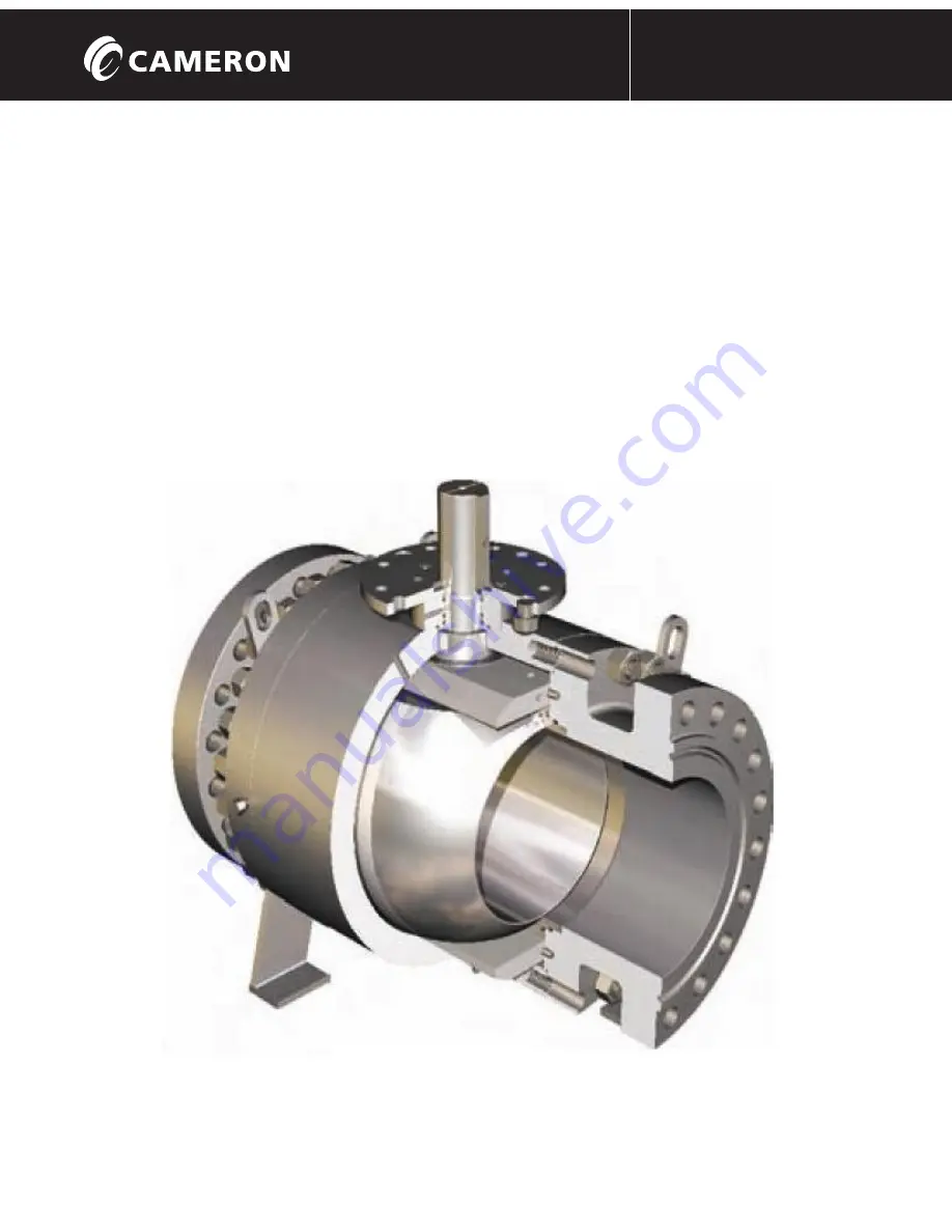
370D5 BALL VALVES
D I S T R I B U T E D V A L V E S
ES-000270
Installation, Operation and Maintenance Manual
W-K-M 370D5
Installation
, Operation and Maintenance Manual
W-K-M
®
370D5 BALL VALVES


