11
Model 753A Gage Pressure Transmitter
Section 3
Piping Guidelines
Observe the following practices when piping for flow and liquid level ap
-
plications.
1. Install the transmitter as near the primary metering device as possible,
and choose a piping diameter accordingly. For distances up to 50 feet,
use 1/4-inch pipe or tubing. For runs of 50 to 100 feet, use 1/2-inch pipe
or tubing.
IMPORTANT: Distances greater than 100 feet should be used only if an air purge or
blow-back system is installed.
2. Slope all piping at least one inch per linear foot to avoid liquid or gas
entrapment in the lines or the instrument.
•
Slope all piping
downward
from the transmitter when used in gas
applications to prevent liquid entrapment.
•
Slope all piping
upward
from the transmitter when used in liquid ap-
plications to prevent liquid entrapment.
3. If the process temperature exceeds 135ºF, provide a minimum of 2 feet
of uninsulated piping between the transmitter and the primary metering
device for each 100 degrees in excess of +135ºF.
4. Install a suitable pulsation dampening device upstream of the transmitter.
Where severe pulsation is present, the accuracy of the flow measurement
will be affected.
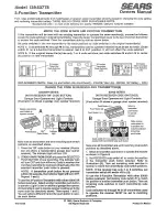
5. For ease of operation and maintenance, install manifolds to allow sens-
ing lines to be shut off while removing the instrument from the line or
performing a calibration.
Appendix A, page 25,
shows an example of a
typical installation configuration.
6.
Locate all shutoff valves so that they are readily accessible from the front
of the instrument. Locate block valves at the source of differential pres
-
sure lines.
7.
Prevent leakage by using a suitable sealing compound on all joints. Mea
-
surement errors can be caused by leaks in the piping.
Electrical Connections
!
WARNING: Ensure that the condulet cover is secure before applying
power to instrument when used in hazardous areas. Failure to do this
may result in personal injury or property damage.
Flexible cable is recommended for electrical connections to the instrument.