background image

p.

2

1

2

1

 - M

a

n

u

a

l c

o

d

e: 

FA

00

13

2

-

E

N
-E

N

 v

2


08

/2

01

6

 © C

A

M

E

 C

a

n

ce

lli A

u

to

m

a

ti

ci

 S

.p.

A

. - T

h

e d

a

ta a

n

d i

n

fo

rm

ati

o

n i

n

 t

h

is

 m

a

n

u

a

l m

ay b

e c

h

a

n

g

e

d at a

n

y time a

n

d wit

h

o

u

t n

o

ti

ce

.

F 30 

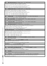
Opening slow-down speed

   15 = Minimum speed / … / 40 = Maximum speed

Setting the boom's opening slow-down speed, calculated as a percentage.

⚠ 

Warning: the speed parameter fi elds vary depending on the type of boom:

- for jointed booms of 2 m, set the slow-down speed percentage to between 20 and 40;
- for booms of 4 m, set the slow-down speed percentage to between 20 and 30;
- for booms of 6 m and 8 m, set the slow-down speed percentage to between 15 and 40.

F31 

Closing slow-down speed

   15 = Minimum speed / … / 40 = Maximum speed

Setting the boom's closing slow-down speed, calculated as a percentage.

⚠ 

Warning: the speed parameter fi elds vary depending on the type of boom:

- for jointed booms of 2 m, set the slow-down speed percentage to between 20 and 40;
- for booms of 4 m, set the slow-down speed percentage to between 20 and 30;
- for booms of 6 m, set the slow-down speed percentage to between 15 and 30;
- for booms of 8 m, set the slow-down speed percentage to between 15 and 20;

F33 Calibration 

speed


20 = 20% of the travel (minimum) / … / 40 = 40% of the travel (maximum)

Setting the boom's travel automatic calibration, calculated as a percentage

F34 

Boom travel sensitivity 


10 = maximum sensitivity / … / 100 = minimum sensitivity (default)

Adjusting obstruction detection sensitivity during boom travel.

F35 Slow-down 

sensitivity


10 = maximum sensitivity / … / 100 = minimum sensitivity (default)

Adjusting obstruction detection sensitivity during slow-down.

F37 

Opening slow-down point


  40 = 40% of the travel / … / 60 = 60% travel

Percentage adjustment of the boom's total travel, from the beginning of the opening slow-down point.
Warning! The percentage varies depending on the boom type:
- for jointed booms of 2 m and 4 m, set the percentage to between 40 and 60;
- for booms of 6 m and 8 m, set the percentage to between 60 and 70.

F38 Closing slow-down point


20 = 20% of the travel /… / 75 = 75% of the travel

Establishing the total travel percentage, from the beginning of the closing slow-down point.
Warning! The percentage varies depending on the boom type:
- for jointed booms and 2-meter booms, set the speed percentage to between 20 and 40;
- for 2 m booms, set the percentage to between 40 and 60;
- for 6 m booms, set the percentage to between 60 and 70;
- for 8 m booms, set the percentage to between 65 and 75;

F 49 

Enabling serial connections


 0 = Deactivated (

default

) / 1 = Paired / 2 = Alternate

To enable paired or alternate operation.

F50 Save 

data


0 = Deactivated (

default

) / 1 = Activated

To save system users and settings in memory roll.

 This function only appears if the memory roll has been fi tted into the control panel.

F51 Read data


0 = Deactivated (

default

) / 1 = Activated

To upload the data saved in the memory roll into the control panel.

 This function only appears if the memory roll has been fi tted into the control panel.

F52 

Passing settings in paired/alternating mode


0 = Deactivated (

default

) / 1 = Activated

Loading parameters of the MASTER barrier into the SLAVE barrier.

 This function appears only if function F 49 is set to either PAIRED or ALTERNATE.

F60 Sleep 

Mode

To reduce the amount of energy consumed by the stand-by photocells.

F61 Pre-fl 

ashing


0 = when opening and closing (default) / 1 = only when closing / 2 = only when opening

After an opening or closing command, the fl ashing light connected to 10-E1m fl ashes before starting the maneuver. 
For setting the time, see function F 21.

Содержание G4040E

Страница 1: ...INSTALLATION AND OPERATION G4040E G4040IE AUTOMATIC BARRIERS FA00132 EN English EN...

Страница 2: ...ARRIER MUST BE CONNECTED TO AN EFFECTIVE REGULATION GROUNDING SYSTEM THE MANUFACTURER DECLINES ANY LIABILITY FOR USING NON ORIGINAL PRODUCTS WHICH WOULD RESULT IN WARRANTY LOSS ALL MAINTAINED ACTION C...

Страница 3: ...hed stainless steel set up for accessories Intended use The automatic barrier is designed for private and public parking facilities Any installation and or use other than that specified in this manual...

Страница 4: ...om attachment cover 5 Protective casing shear proof 6 Cabinet 7 Anchoring pin 8 Control panel 9 Boom setting mechanical stop 10 Lever arm 11 Gearmotor with encoder 12 Inspection hatch 13 Anchoring bra...

Страница 5: ...e electric cables to pass through making sure they are protected from any mechanical damage Tools and materials Make sure you have all the tools and materials you will need for installing in total saf...

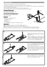
Страница 6: ...mpletely fastened Preparing the fastening plate If the flooring does not allow for a sturdy fastening of the entry unit you will have to set up a cement slab Dig a hole for the foundation frame Set up...

Страница 7: ...atch Warning The barrier is set up for installing on the left When installing on the right invert the boom s opening direction as follows remove the anchoring pin from the lever arm release the gearmo...

Страница 8: ...te and motor shaft plate with a screw Leave the screw loose to then facilitate fitting the boom To mount with the G03750 boom you will need to fit the G03756 reinforcement Attachment plate Mid plate B...

Страница 9: ...ny time and without notice Fit the boom into the boom attachment cover and fasten it using the screws Cut the groove cover profiles to measure and fit them into the grooves on both sides of the boom F...

Страница 10: ...ease the gearmotor and position the boom vertically Lock the gearmotor again Tighten the eyelet rod under the spring The spring should be screwed to the anchoring pin PASSAGE CLEARANCE 8 max 3 75 m Th...

Страница 11: ...t notice Fasten the counter nut and lock the gearmotor again Check the proper working state of the spring With the boom raised vertically the spring is not taut With the boom lowered horizontally the...

Страница 12: ...rd connector 13 AF card connector 14 Antenna terminal 15 Terminals for control and safety devices 16 Terminals for paired alternate CRP connections 17 Keypad selector terminal 18 Terminals for transpo...

Страница 13: ...pply Terminals for powering up accessories a 24 V AC normally a 24 V DC when the emergency batteries are operating Overall allowed power 40 W Transformer Red White Blue Orange 24 V DC gearmotor with e...

Страница 14: ...ed select 0 Deactivated from function F1 OPEN CLOSE INVERT function step step from control device NO contact Keypad selector Transponder or card reader Fit the R700 decoding card for recognition of th...

Страница 15: ...devices C9 immediate closing with obstruction wait when closing Closing the boom after a vehicle has passed through the operating area of the safety devices During the closing phase the devices also p...

Страница 16: ...16 16 Manual code FA00132 E N E N v 2 2 08 2016 CAME Cancelli Automatici S p A The data and information in this manual may be changed at any time and without notice Sleep Mode The Sleep mode function...

Страница 17: ...the stop with a counter nut Establishing the endstop points Close the inspection hatch and power up the system Activate the barrier to check whether the boom is parallel to the road surface when close...

Страница 18: ...ENTER also for the submenus use the arrow keys to select To increase or reduce the value use the arrows to exit the menu wait 10 seconds or press ESC the press ENTER to confirm Browsing the menu then...

Страница 19: ...ctions F 50 Saving data in memory roll F 51 Reading memory roll data F 52 Transferring parameters from Master to Slave F 60 Sleep Mode function F 61 Pre flashing function U 1 Type of command to associ...

Страница 20: ...ing and closing The cycle lamp stays on from the moment in which the barrier starts opening until it closes completely including the automatic closing time In case the automatic closing is not inserte...

Страница 21: ...avel Percentage adjustment of the boom s total travel from the beginning of the opening slow down point Warning The percentage varies depending on the boom type for jointed booms of 2 m and 4 m set th...

Страница 22: ...oom type The choice of boom type limits certain speed slow down and calibration limits This is to safeguard the entire barrier A 2 Motor test 0 Disable 1 Activate To verify the boom s proper rotating...

Страница 23: ...s ENTER to confirm that the barrier has cali brated itself automatically Travel calibration Before doing a travel calibration establish the boom type check that the boom is balanced and that the maneu...

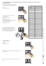
Страница 24: ...NTER to confirm 2 Select a command to associate to the user The commands are step step open close 1 open 3 partial opening pedestrian 4 The partial pedestrian command appears only of function F 49 is...

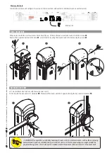
Страница 25: ...Memory Roll Card To memorize user data and configure the system to then reuse them with another control board even on another system RELEASING THE BOOM This procedure must be done with the main power...

Страница 26: ...MASTER control panel Important Deactivate function F 19 automatic closing time on the SLAVE barrier s control panel Configuring the MASTER operator Select function F 49 Press ENTER to con rm Select 1...

Страница 27: ...the MASTER barrier ALTERNATE CONNECTION Important Start by performing the following procedures on both operators t the RSE card with DIP switches sent to OFF onto the control panel connector of both b...

Страница 28: ...e power supply and fuses The barrier does not perform automatic closing 11 12 13 4 The NC contacts are open The barrier does not work with the transmitter 2 14 16 6 Deactivate the MASTER SLAVE functio...

Страница 29: ...ion in this manual may be changed at any time and without notice Periodic maintenance Before doing any maintenance cut off the power supply to prevent any hazardous situations caused by accidental boo...

Страница 30: ...__________________ Fitter s stamp Name of operator Job performed on date Technician s signature Requester s signature Job performed ____________________________________________________________________...

Страница 31: ...e disposed of as solid urban waste and simply separated from other waste for recycling Always make sure you comply with local laws before dismantling and disposing of the product DO NOT DISPOSE OF IN...

Страница 32: ...3079 Sesto al Reghena Sesto al Reghena Pordenone Pordenone Italy 39 0422 4940 39 0422 4941 39 0434 698111 39 0434 698434 E n g l i s h E n g l i s h Manual code FA 0 013 2 E N FA 0 013 2 E N v 2 2 08...

Отзывы: