LP
LG
1
2
140
LO
CK
UN
LO
CK
CA
ME
CAME
L N
L N
CAME
LN
LN - 30
30
4
3
5
150
4
3
5
150
Ⓑ
Ⓐ
p.
44
- M
an
ua
l c
od
e
FA
017
53
-E
N
FA
017
53
-E
N
- 0
1/
20
22 - © C
am
e S
.p
.A
. T
he c
on
te
nt
s o
f t
hi
s m
an
ua
l m
ay b
e c
ha
ng
ed a
t a
ny t
im
e w
ith
ou
t p
rio
r n
ot
ic
e.
INSTALLATION
⚠
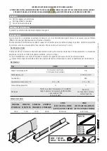
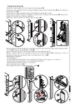
Before installing, check that the sensitive safety-edge is to be fastened onto a suitable surface.
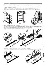
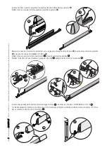
Setting up the sensitive safety-edge.
For non standard length sensitive safety-edges, establish the LN or nominal length of the area you with to protect.
Warning! With vertical fittings, reduce the LN by 30 to the edge from scraping the ground.
Use a Ø 3-mm bt to drill the rail on either side for fitting the end caps
.
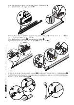
Fit marked end of the cable-clamping mechanism into the rail
and fasten it using the two UNI6955 Ø 3.9x13 screws
.
Cut the rubber edge LG = LN - 285 mm
.
⚠
Products DFWN1500/1700/2000/2500 have a narrowing on the aluminum rail
Ⓐ
. When assembling, mark the
aluminum rail 140 mm from the end. Use channellock pliers
Ⓑ
.
Cutthe aluminum rail at the opposite end of the point marked LP = LN - 40 mm
.

