background image


15

 - Manuel 

FA01310-FR

  - 02/2020 - © C

AME S.p.A. - L

e contenu de ce manuel est susceptible de subir des modifications à tout moment et sans aucun pr

éavis. - T

raduction des instructions originales

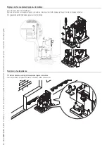
Réglage de l’accouplement pignon-crémaillère

Ouvrir et fermer le portail manuellement.
Régler la distance de l'accouplement pignon-crémaillère à l'aide des pieds filetés (réglage vertical) et des fentes (réglage horizontal).

 Le poids du portail ne doit pas peser sur l’automatisme.

1 ÷ 2

Fixation de l'automatisme

 Ne fixer qu’après avoir réglé l'accouplement pignon-crémaillère.

Fixer l’automatisme à la plaque de fixation à l'aide des butées et des écrous.

Содержание BX704AGS

Страница 1: ...Automazioni per cancelli scorrevoli BX704AGS BX704ALS BX708AGS BX708RGS BX708ALS MANUALE DI INSTALLAZIONE FA01310M04 IT Italiano EN English FR Français RU Русский ...

Страница 2: ...2 Manuale FA01310 IT 02 2020 CAME S p A I contenuti del manuale sono da ritenersi suscettibili di modifica in qualsiasi momento senza obbligo di preavviso Istruzioni originali 2 3 1 2 3 1 ...

Страница 3: ...bambini Nel caso di movimentazione manuale prevedere una persona per ogni 20 kg da sollevare nel caso di movimentazione non manuale utilizzare opportuni mezzi per il sollevamento in sicurezza Si raccomanda di utilizzare adeguate protezioni per evitare possibili pericoli meccanici dovuti alla presenza di persone nel raggio d azione dell automazione I cavi elettrici devono passare attraverso apposit...

Страница 4: ...ALTIMENTO DELL IMBALLO I componenti dell imballo cartone plastiche etc sono assimilabili ai rifiuti solidi urbani e possono essere smaltiti senza alcuna difficoltà semplicemente effettuando la raccolta differenziata per il riciclaggio Prima di procedere è sempre opportuno verificare le normative specifiche vigenti nel luogo d installazione NON DISPERDERE NELL AMBIENTE SMALTIMENTO DEL PRODOTTO I no...

Страница 5: ...vazione dell ostacolo e finecorsa meccanici per cancelli scorrevoli fino a 800 kg e 14 m di lunghezza 801MS 0021 BX704ALS Automazione completa di scheda elettronica con display di programmazione decodifica radio incorporata dispositivo per il controllo del movimento e rilevazione dell ostacolo e finecorsa meccanici per cancelli scorrevoli fino a 400 kg e di lunghezza max 14 m 801MS 0031 BX708ALS A...

Страница 6: ...oni originali Descrizione delle parti Automazione 1 Coperchio 2 Coperchio frontale 3 Motoriduttore 4 Condensatore 5 Finecorsa meccanico 6 Piastra di fissaggio 7 Supporto per scheda elettronica 8 Scheda elettronica 9 Alette di finecorsa 10 Trasformatore 11 Sportello di sblocco 12 Minuteria di fissaggio 13 Staffe di montaggio per alloggiamento accessori opzionale ...

Страница 7: ... il collegamento del motoriduttore 3 Morsettiera per il collegamento del trasformatore 4 Fusibile per la scheda elettronica 5 Morsettiera per il collegamento dei dispositivi di comando e di sicurezza 6 Fusibile per gli accessori 7 Morsettiera per il collegamento del modulo RGP1 8 Morsettiera per il collegamento dell Encoder 9 Morsettiera per il collegamento del selettore a tastiera 10 Morsettiera ...

Страница 8: ...y con il modulo RGP1 W 0 8 0 8 0 8 0 8 0 8 Potenza W 560 520 560 520 530 Condensatore μF 12 20 12 20 80 Corrente assorbita A 2 7 2 5 2 7 2 5 4 5 Colore RAL 7024 RAL 7024 RAL 7040 RAL 7040 RAL 7024 Temperatura d esercizio C 20 55 20 55 20 55 20 55 20 55 Spinta N 600 800 600 800 800 Velocità massima di manovra m min 10 5 10 5 10 5 10 5 10 5 Cicli ora 17 17 17 17 17 Cicli consecutivi 6 6 6 6 6 Interm...

Страница 9: ...i a temperatura ambiente di 20 C come definito dalla Norma EN 60335 2 103 MODELLI BX704AGS BX708AGS BX704ALS BX708ALS BX708RGS Cicli ora n 17 17 17 17 17 Cicli consecutivi n 6 6 6 6 6 Lunghezza standard di riferimento della parte scorrevole m 4 4 4 4 4 Per cancelli con una parte scorrevole di lunghezza diversa da quella standard di riferimento utilizzare i grafici Grafico cicli ora A Numero di cic...

Страница 10: ...mi alla 60245 IEC 57 IEC in ambiente interno invece utilizzare cavi tipo H05VV F conformi alla 60227 IEC 53 IEC Per alimentazioni fino a 48 V si possono utilizzare cavi tipo FROR 20 22 II conformi alla EN 50267 2 1 CEI Per il collegamento dell antenna utilizzare cavo tipo RG58 consigliato fino a 5 m Per il collegamento abbinato e CRP utilizzare cavo tipo UTP CAT5 fino a 1000 m Qualora i cavi abbia...

Страница 11: ...omazione installata a sinistra Operazioni preliminari Fare lo scavo per la cassa matta Preparare i tubi corrugati necessari per i collegamenti provenienti dal pozzetto di derivazione Per il collegamento del motoriduttore e degli accessori si consigliano tubi corrugati Ø 40 mm Il numero di tubi dipende dal tipo di impianto e dagli accessori previsti 3 0 0 500 45 0 Posa della piastra di fissaggio Pr...

Страница 12: ...glia di ferro I tubi devono passare attraverso i fori predisposti 2 1 UNI 5739 12 X 70 M12 Posizionare la piastra di fissaggio rispettando le misure riportate sul disegno Se il cancello non ha la cremagliera procedere con l installazione Vedere il paragrafo FISSAGGIO DELLA CREMAGLIERA Riempire la cassa matta di cemento La piastra deve essere perfettamente in bolla e con il filetto delle viti compl...

Страница 13: ...ili di modifica in qualsiasi momento senza obbligo di preavviso Istruzioni originali Togliere i dadi dalle viti Inserire i cavi elettrici nei tubi fino a farli uscire di 600 mm circa Preparazione dell automazione Rimuovere il coperchio frontale 1 2 3 Rimuovere il coperchio dell automazione 4 5 ...

Страница 14: ...ell automazione Sollevare l automazione di 5 10 mm dalla piastra agendo sui piedini filettati per permettere eventuali regolazioni successive tra pignone e cremagliera 5 10 Fissaggio della cremagliera 1 Sbloccare l automazione 2 Appoggiare la cremagliera sul pignone 3 Saldare o fissare la cremagliera al cancello in tutta la sua lunghezza Per assemblare i moduli della cremagliera utilizzare un pezz...

Страница 15: ...prire e chiudere il cancello manualmente Registrare la distanza dell accoppiamento pignone cremagliera con i piedini filettati regolazione verticale e le asole regolazione orizzontale Il peso del cancello non deve gravare sull automazione 1 2 Fissaggio dell automazione Procedere al fissaggio solo dopo aver regolato l accoppiamento pignone cremagliera Fissare l automazione alla piastra di fissaggio...

Страница 16: ...sa meccanici 1 Aprire il cancello 2 Infilare l aletta di finecorsa di apertura sulla cremagliera La molla deve far scattare il micro 3 Fissare l aletta di finecorsa di apertura con le viti senza testa fornite 1 2 20 mm 4 Chiudere il cancello 5 Infilare l aletta di finecorsa di chiusura sulla cremagliera La molla deve far scattare il micro 6 Fissare l aletta di finecorsa di chiusura con le viti sen...

Страница 17: ...Utilizzare dei pressacavi per collegare i dispositivi al quadro comando Uno di questi deve essere destinato esclusivamente per il cavo di alimentazione 1 Passacavi del supporto scheda Alimentazione Durante tutte le fasi dell installazione assicurarsi di operare fuori tensione Prima di intervenire sul quadro di comando togliere la tensione di linea e se presenti scollegare le batterie Collegamento ...

Страница 18: ... 12 24 1 2 3 4 L1T 0 1 2 3 6 5 4 7 1 Cavo bianco 2 Cavo nero 3 Cavo rosso 4 Cavo blu 5 Cavo viola 6 Cavo arancione 7 Per variare la coppia motore spostare il faston indicato su una delle 4 posizioni da 1 minimo a 4 massimo Dispositivi di segnalazione 1 Lampeggiatore Lampeggia durante le fasi di apertura e chiusura dell automazione 2 Lampada supplementare Aumenta l illuminazione nella zona di manov...

Страница 19: ...azione 5 Dispositivo di comando contatto NO Funzione APERTURA PARZIALE 6 Dispositivo di comando contatto NO Funzione APRE CHIUDE passo passo o APRE STOP CHIUDE STOP sequenziale 7 Antenna con cavo RG58 S1GND A B 3 2 1 5 6 4 7 Dispositivi di sicurezza In fase di programmazione configurare il tipo di azione che deve essere svolta dal dispositivo collegato all ingresso Collegare i dispositivi di sicur...

Страница 20: ...i modifica in qualsiasi momento senza obbligo di preavviso Istruzioni originali Fotocellule DIR DELTA S Collegamento standard Fotocellule DIR DELTA S Collegamento con test di sicurezza Vedi funzione F5 test sicurezze 10 2 TX C NC TX 2 RX TX 10 2 TX C NC TX 2 RX TX Bordo sensibile DFWN C NO NC DFWN ...

Страница 21: ...ne deve essere effettuata solo da personale esperto e qualificato Controllare che l area di manovra sia libera da qualsiasi ostacolo Dare tensione e procedere con la programmazione Iniziare la programmazione con le funzioni di seguito indicate F54 Direzione apertura Imposta la direzione di apertura del cancello F1 Stop totale Arresta il cancello ed esclude l eventuale chiusura automatica Usare un ...

Страница 22: ... Stop parziale Solo con Ch automatica attivata C4 Attesa ostacolo Fotocellule C7 Riapertura durante la chiusura bordi sensibili C8 Richiusura durante l apertura Bordi sensibili r7 riapertura durante la chiusura Bordi sensibili con resistenza 8K2 r8 richiusura durante l apertura Bordi sensibili con resistenza 8K2 Test sicurezze Attiva il controllo del corretto funzionamento delle fotocellule colleg...

Страница 23: ...mpada rimane spenta se non viene impostato un tempo di chiusura automatica Chiusura automatica Imposta il tempo che deve trascorrere prima che si attivi la chiusura automatica una volta che è stato raggiunto il punto di finecorsa in apertura La funzione non si attiva nei casi in cui intervengano dispositivi di sicurezza per la rilevazione di un ostacolo dopo uno stop totale o in caso di mancanza d...

Страница 24: ...ne Encoder F35 Sensibilità rallentamento da 10 a 100 Default 100 10 massima sensibilità 100 minima sensibilità Punto di apertura parziale Determina in percentuale sulla corsa totale il punto di apertura parziale del cancello Questa funzione compare solo se è attiva la funzione Encoder F36 Punto ap parziale da 10 a 80 80 Default Punto di rallentamento in apertura Imposta il punto di inizio del rall...

Страница 25: ... sul cancello Master con il cancello Slave Questa funzione compare solo se è attiva la funzione RSE F52 Passaggio parametri MASTER SLAVE OFF Default ON Direzione apertura Imposta la direzione di apertura del cancello F54 Direzione apertura 0 Verso sinistra Default 1 Verso destra Indirizzo CRP Assegna un codice identificativo univoco indirizzo CRP alla scheda elettronica La funzione è necessaria ne...

Страница 26: ... di associare una funzione tra quelle previste a un dispositivo di sicurezza wireless La funzione appare solo se è presente una scheda di interfaccia per dispositivi wireless F68 RIO PH T2 OFF Default P1 Riapertura durante la chiusura P2 Richiusura durante l apertura P3 Stop parziale P4 Attesa ostacolo Tempo apertura parziale Permette di regolare il tempo di apertura del cancello F71 Tempo apertur...

Страница 27: ...zione Scegliendo il tipo di codifica radio dei trasmettitori Rolling code o TW key block eventuali trasmettitori con codifica radio diversa precedentemente memorizzati verranno cancellati U4 Decodifica radio 1 Tutte le decodifiche Default 2 Rolling code 3 TW Key Block Tipo motore Imposta il tipo di motoriduttore installato A1 Tipo motore 1 BX704 2 BX708 Taratura corsa Avvia l auto apprendimento de...

Страница 28: ... estrarre la scheda MEMORY ROLL è OBBLIGATORIO TOGLIERE LA TENSIONE DI LINEA 1 Inserire la scheda MEMORY ROLL sul connettore dedicato presente sulla scheda elettronica 2 Premere il pulsante Enter per accedere alla programmazione 3 Usare le frecce per scegliere la funzione desiderata Le funzioni vengono visualizzate solo quando viene inserita una scheda MEMORY ROLL Salvataggio dati Salva nel dispos...

Страница 29: ...ttura encoder E4 Errore di test servizi fallito E7 Errore tempo di lavoro E8 Errore sportello sblocco aperto Verificare che il fusibile accessori non sia bruciato E9 Ostacolo rilevato durante la chiusura E10 Ostacolo rilevato durante l apertura E11 Superato il numero massimo di ostacoli rilevati consecutivamente E15 Errore trasmettitore non compatibile E17 Errore sistema wireless non comunica E18 ...

Страница 30: ...no collegati sulla scheda elettronica che verrà impostata come MASTER Per i collegamenti elettrici dei dispositivi e degli accessori vedere capitolo COLLEGAMENTI ELETTRICI RSE A B GND UTP CAT5 max 1000m RSE A B GND Programmazione Tutte le operazioni di programmazione di seguito descritte vanno eseguite solo sulla scheda elettronica impostata come MASTER F49 RSE Configura la funzione che deve svolg...

Страница 31: ...e l impianto non viene utilizzato per lunghi periodi per esempio nel caso di installazioni in luoghi ad apertura stagionale è opportuno togliere l alimentazione e al ripristino verificare il corretto funzionamento Per le informazioni relative alla corretta installazione e alle regolazioni consultare il manuale di installazione del prodotto Per le informazioni relative alla scelta del prodotto e de...

Страница 32: ...contenuti del manuale sono da ritenersi suscettibili di modifica in qualsiasi momento senza obbligo di preavviso Istruzioni originali CAME S p A Via Martiri della Libertà 15 31030 Dosson di Casier Treviso Italy Tel 39 0422 4940 Fax 39 0422 4941 ...

Страница 33: ...Sliding gate operators BX704AGS BX704ALS BX708AGS BX708RGS BX708ALS INSTALLATION MANUAL FA01310 EN EN English ...

Страница 34: ...2 Manual FA01310 EN 02 2020 CAME S p A The contents of this manual may be changed at any time and without notice Translation of the original instructions 2 3 1 2 3 1 ...

Страница 35: ...he entire site properly to prevent unauthorised personnel from entering especially minors In case of manual handling have one person for every 20 kg that needs hoisting for non manual handling use proper hoisting equipment in safe conditions Use suitable protection to prevent any mechanical hazards due to persons loitering within the operating range of the operator The electrical cables must pass ...

Страница 36: ...ply follow these brief disposal guidelines DISPOSING OF THE PACKAGING The packaging materials cardboard plastic etc can be disposed of easily as solid urban waste separated for recycling Before dismantling and disposing of the product please always check the local laws in force DISPOSE OF THE PRODUCT RESPONSIBLY DISPOSING OF THE PRODUCT Our products are made of various materials Most of these mate...

Страница 37: ...vice and mechanical limit switches for sliding gates weighing up to 800 kg that are up to 14 m in length 801MS 0021 BX704ALS Operator complete with control board with programming display built in radio decoder movement and obstruction detection device and mechanical limit switches for sliding gates weighing up to 400 kg that are up to 14 m in length 801MS 0031 BX708ALS Operator complete with contr...

Страница 38: ...ion of the original instructions Description of parts Operator 1 Cover 2 Front cover 3 Gearmotor 4 Capacitor 5 Mechanical limit switch 6 Anchoring plate 7 Control board holder 8 Control board 9 Limit switch tabs 10 Transformer 11 Release hatch 12 Fixtures and fittings 13 Assembly brackets for housing accessories optional ...

Страница 39: ... board for connecting the gearmotor 3 Terminal board for connecting the transformer 4 Control board fuse 5 Terminal board for connecting control and safety devices 6 Accessories fuse 7 Terminal board for connecting the RGP1 module 8 Terminal board for connecting the encoder 9 Terminal board for connecting the keypad selector 10 Terminal board for connecting the limit switches 11 Terminal board for...

Страница 40: ...y consumption with the RGP1 W module 0 8 0 8 0 8 0 8 0 8 Power W 560 520 560 520 530 Capacitor μF 12 20 12 20 80 Current draw mA 2 7 2 5 2 7 2 5 4 5 Colour RAL 7024 RAL 7024 RAL 7040 RAL 7040 RAL 7024 Operating temperature C 20 55 20 55 20 55 20 55 20 55 Thrust N 600 800 600 800 800 Maximum operating speed m min 10 5 10 5 10 5 10 5 10 5 Cycles hour 17 17 17 17 17 Consecutive cycles 6 6 6 6 6 Duty ...

Страница 41: ...an ambient temperature of 20 C as stated in EN standard 60335 2 103 MODELS BX704AGS BX708AGS BX704ALS BX708ALS BX708RGS Cycles hour no 17 17 17 17 17 Consecutive cycles no 6 6 6 6 6 Standard reference length of the sliding part m 4 4 4 4 4 For gates where the sliding part is of a different length to the standard measurement please see the graphs Cycles hour graph A Number of cycles B Gate length 0...

Страница 42: ... 230 V and outdoors use H05RN F cables compliant with 60245 IEC 57 IEC when operating indoors use H05VV F cables compliant with 60227 IEC 53 IEC For power supplies up to 48 V you can use FROR 20 22 II cables compliant with EN 50267 2 1 CEI To connect the antenna use RG58 cable up to 5 m For paired connection and CRP use UTP CAT5 cable up to 1 000 m If the cable lengths differ from those specified ...

Страница 43: ... fitted on the left Preliminary operations Dig a hole for the foundation frame Set up the corrugated tubes needed for the wiring coming out of the junction pit Use Ø 40 mm corrugated tubes to connect the gearmotor to the accessories The number of tubes depends on the type of system and the accessories that are going to be fitted 3 0 0 500 45 0 Laying the anchoring plate Set up a foundation frame t...

Страница 44: ...late in the iron cage The tubes must pass through the existing holes 2 1 UNI 5739 12 X 70 M12 Position the anchoring plate taking note of the measurements shown in the drawing If the gate does not have a rack proceed with the installation See the section FASTENING THE RACK Cast cement into the foundation frame The plate must be perfectly level and the screw threads completely above surface Wait at...

Страница 45: ... changed at any time and without notice Translation of the original instructions Remove the nuts from the screws Insert the electrical cables into the tubes until they protrude by about 600 mm Setting up the operator Remove the front cover 1 2 3 Remove the operator cover 4 5 ...

Страница 46: ... the operator foundation frame Lift the operator by 5 10 mm from the plate by adjusting the threaded feet to allow for any adjustments that may need to be made between the rack and pinion 5 10 Fastening the rack 1 Release the operator 2 Rest the rack on the pinion 3 Weld or fasten the rack to the gate along its entire length To assemble the rack modules use an extra piece and rest it under the joi...

Страница 47: ...ling Open and close the gate manually Adjust the pinion rack coupling distance using the threaded feet vertical adjustment and the holes horizontal adjustment The weight of the gate must not bear down upon the operator 1 2 Fastening the operator in place Only fasten the operator after adjusting the pinion rack coupling Fasten the operator to the anchoring plate using stoppers and nuts ...

Страница 48: ...echanical limit switches 1 Open the gate 2 Insert the opening limit switch tab in the rack The spring must trigger the microswitch 3 Fasten the opening limit switch tab using the grub screws supplied 1 2 20 mm 4 Close the gate 5 Insert the closing limit switch tab in the rack The spring must trigger the microswitch 6 Fasten the closing limit switch tab using the grub screws supplied 2 2 1 20 mm ...

Страница 49: ...cable glands to connect the devices to the control panel One of these must be used exclusively for the power supply cable 1 Cable glands on the board holder Power supply Make sure the mains power supply is disconnected during all installation procedures Before working on the control panel disconnect the mains power supply and remove the batteries if any Connecting to the mains 120 230 V AC 50 60 H...

Страница 50: ... 3 6 5 4 7 1 White cable 2 Black cable 3 Red cable 4 Blue cable 5 Purple cable 6 Orange cable 7 To vary the motor torque move the corresponding Faston terminal to one of the four positions from 1 minimum to 4 maximum Signalling devices 1 Flashing beacon It flashes when the operator opens and closes 2 Additional light It increases the light in the manoeuvring area 3 Operator status warning light It...

Страница 51: ... Control device NO contact PARTIAL OPENING function 6 Control device NO contact OPEN CLOSE step by step or OPEN STOP CLOSE STOP sequential function 7 Antenna with RG58 cable S1GND A B 3 2 1 5 6 4 7 Safety devices During programming configure the type of action that must be performed by the device connected to the input Connect the safety devices to the CX and or CY inputs If contacts CX and or CY ...

Страница 52: ... at any time and without notice Translation of the original instructions DIR DELTA S photocells Standard connection DIR DELTA S photocells Connection with safety test See function F5 safety devices test 10 2 TX C NC TX 2 RX TX 10 2 TX C NC TX 2 RX TX DFWN sensitive edge C NO NC DFWN ...

Страница 53: ...ons indicated below F54 Opening direction Set the gate opening direction F1 Total stop Stop the gate and exclude automatic closing Use a control device to resume movement A3 Travel calibration Start the travel self learning After powering up the system the first manoeuvre is always to open the gate Wait for the manoeuvre to be completed Press the STOP button immediately in the event of any faults ...

Страница 54: ...fter each opening and closing command F5 Safety devices test OFF Default 1 CX 2 CY 4 CX CY Hold to run With the function active the operator stops moving opening or closing when the control device is released When the function is active it excludes all other control devices F6 Hold to run OFF Default ON Command 2 7 Associate a command with the device connected to 2 7 F7 Command 2 7 0 Step by step ...

Страница 55: ...Automatic closing after partial opening Set the time before automatic closure is activated after a partial opening command has been performed The function does not work if any of the safety devices are triggered when an obstacle is detected or after a complete stop or during a power outage Do not deactivate the function Automatic close F20 Automatic partial close OFF From 1 to 180 seconds default ...

Страница 56: ...t 15 Closing slowdown point Set the closing slowdown start point as a percentage of total travel This function appears only if the Encoder function is active F38 Closing slowdown point 5 to 30 Default 15 Manoeuvre thrust activation Increase the thrust torque during opening and closing F48 Manoeuvre thrust activation OFF Default ON RSE Configure the function to be performed by the card inserted in ...

Страница 57: ... 1 to 255 RSE speed Set the remote connection system communication speed on the RSE port F63 RSE speed 0 1200 bps 1 2400 bps 2 4800 bps 3 9600 bps 4 14400 bps 5 19200 bps 6 38400 bps default 7 57600 bps 8 115200 bps RIO ED T1 Associate one of the available functions to a wireless safety device The function only appears if there is an interface board for wireless devices F65 RIO ED T1 OFF Default P...

Страница 58: ... default 5 seconds New user Register up to a maximum of 250 users and assign a function to each one The operation can be carried out by using a transmitter or another control device The boards that manage the control devices AF R700 R800 must be inserted into the connectors Download the LIST OF REGISTERED USERS form from the docs came com portal by typing in L20180423 U1 New user 1 Step by step 2 ...

Страница 59: ...g code 3 TW key block Motor type Set the type of gearmotor installed A1 Motor type 1 BX704 2 BX708 Travel calibration Start the travel self learning This function appears only if the Encoder function is active A3 Travel calibration OFF Default ON Parameter reset Restore factory settings except for the functions Radio decoding Motor type and the settings related to travel calibration A4 Parameter r...

Страница 60: ...MORY ROLL card DISCONNECT THE MAINS POWER SUPPLY TO THE LINE 1 Insert the MEMORY ROLL card into the corresponding connector on the control board 2 Press the Enter button to access programming 3 Use the arrows to choose the desired function The functions are displayed only when a MEMORY ROLL card is inserted Save data Save user data timings and configurations to the memory device memory roll or USB...

Страница 61: ...failure error E4 Service test failure error E7 Operating time error E8 Open release hatch error Check that the accessories fuse is not blown E9 Obstacle detected during closing E10 Obstacle detected during opening E11 The maximum number of obstacles detected consecutively has been exceeded E15 Incompatible transmitter error E17 Wireless system communication error E18 Wireless system not configured...

Страница 62: ... to the control board which will be set as the MASTER For information on connecting the electrics for the devices and accessories please see the ELECTRICAL CONNECTIONS section RSE A B GND UTP CAT5 max 1000m RSE A B GND Programming All programming operations described below must be performed only on the control board set as the MASTER F49 RSE Configure the function to be performed by the card inser...

Страница 63: ...f the system is not used for long periods of time e g for installations at sites with seasonal closures disconnect the power supply When the power supply is reconnected check the system is working correctly For information on correct installation and adjustments please see the product installation manual For information on choosing products and accessories please see our product catalogue Every 10...

Страница 64: ...E S p A The contents of this manual may be changed at any time and without notice Translation of the original instructions CAME S p A Via Martiri della Libertà 15 31030 Dosson di Casier Treviso Italy Tel 39 0422 4940 Fax 39 0422 4941 ...

Страница 65: ...Automatismes pour portails coulissants BX704AGS BX704ALS BX708AGS BX708RGS BX708ALS MANUEL D INSTALLATION FA01310 FR FR Français ...

Страница 66: ...2 Manuel FA01310 FR 02 2020 CAME S p A Le contenu de ce manuel est susceptible de subir des modifications à tout moment et sans aucun préavis Traduction des instructions originales 2 3 1 2 3 1 ...

Страница 67: ...n d en éviter l accès aux personnes non autorisées notamment aux mineurs et aux enfants En cas de manutention manuelle prévoir une personne tous les 20 kg à soulever en cas de manutention non manuelle utiliser des instruments aptes à assurer le levage sécurisé Adopter des mesures de protection adéquates contre tout danger mécanique lié à la présence de personnes dans le rayon d action de l automat...

Страница 68: ...composants de l emballage carton plastiques etc sont assimilables aux déchets urbains solides et peuvent être éliminés sans aucune difficulté en procédant tout simplement à la collecte différenciée pour le recyclage Avant d effectuer ces opérations il est toujours recommandé de vérifier les normes spécifiques en vigueur sur le lieu d installation NE PAS JETER DANS LA NATURE ÉLIMINATION DU PRODUIT ...

Страница 69: ...uvement détection d obstacle et fins de course mécaniques pour portails coulissants jusqu à 800 kg et max 14 m de longueur 801MS 0021 BX704ALS Automatisme avec carte électronique à afficheur de programmation décodage radio incorporé dispositif de contrôle du mouvement détection d obstacle et fins de course mécaniques pour portails coulissants jusqu à 400 kg et max 14 m de longueur 801MS 0031 BX708...

Страница 70: ...ons originales Description des parties Automatisme 1 Couvercle 2 Couvercle frontal 3 Motoréducteur 4 Condensateur 5 Fin de course mécanique 6 Plaque de fixation 7 Support pour carte électronique 8 Carte électronique 9 Ailettes de fin de course 10 Transformateur 11 Volet de déblocage 12 Éléments de fixation 13 Étriers de fixation du logement des accessoires en option ...

Страница 71: ...nier d alimentation 2 Bornier de connexion du motoréducteur 3 Bornier de connexion du transformateur 4 Fusible pour la carte électronique 5 Bornier de connexion des dispositifs de commande et de sécurité 6 Fusible pour les accessoires 7 Bornier de connexion du module RGP1 8 Bornier de connexion de l encodeur 9 Bornier de connexion du clavier à code 10 Bornier de connexion des butées de fin de cour...

Страница 72: ...n stand by avec le module RGP1 W 0 8 0 8 0 8 0 8 0 8 Puissance W 560 520 560 520 530 Condensateur μF 12 20 12 20 80 Courant absorbé A 2 7 2 5 2 7 2 5 4 5 Couleur RAL 7024 RAL 7024 RAL 7040 RAL 7040 RAL 7024 Température de fonctionnement C 20 55 20 55 20 55 20 55 20 55 Poussée N 600 800 600 800 800 Vitesse de manœuvre max m min 10 5 10 5 10 5 10 5 10 5 Cycles heure 17 17 17 17 17 Cycles consécutifs...

Страница 73: ...t mesurés à une température ambiante de 20 C conformément à la Norme EN 60335 2 103 MODÈLES BX704AGS BX708AGS BX704ALS BX708ALS BX708RGS Cycles heure 17 17 17 17 17 Cycles consécutifs 6 6 6 6 6 Longueur standard de référence de la partie coulissante m 4 4 4 4 4 Pour les portails avec une partie coulissante d une longueur différente de la longueur de référence standard utiliser les graphiques Graph...

Страница 74: ...es à la norme 60245 IEC 57 IEC en intérieur utiliser par contre des câbles H05VV F conformes à la norme 60227 IEC 53 IEC Pour les alimentations jusqu à 48 V il est possible d utiliser des câbles FROR 20 22 II conformes à la norme EN 50267 2 1 CEI Pour la connexion de l antenne utiliser un câble RG58 jusqu à 5 m Pour la connexion vis à vis et CRP utiliser un câble UTP CAT5 jusqu à 1000 m Si la long...

Страница 75: ...iquée Les dessins illustrent l automatisme installé à gauche Opérations préliminaires Creuser la fosse pour le coffrage Préparer les gaines annelées pour les raccordements issus du boîtier de dérivation Il est conseillé de prévoir des gaines annelées Ø 40 mm pour la connexion du motoréducteur et des accessoires Le nombre de gaines dépend du type d installation et des accessoires prévus 3 0 0 500 4...

Страница 76: ... de fixation dans la grille en fer Les tuyaux doivent passer à travers les trous prévus 2 1 UNI 5739 12 X 70 M12 Positionner la plaque de fixation selon les dimensions indiquées sur le dessin Si le portail est sans crémaillère procéder à l installation Voir le paragraphe FIXATION DE LA CRÉMAILLÈRE Remplir le coffrage de ciment La plaque doit être parfaitement nivelée et avec le filet des vis total...

Страница 77: ...ons à tout moment et sans aucun préavis Traduction des instructions originales Enlever les écrous des vis Introduire les câbles électriques dans les gaines jusqu à ce qu ils sortent d environ 600 mm Préparation de l automatisme Enlever le couvercle frontal 1 2 3 Enlever le couvercle de l automatisme 4 5 ...

Страница 78: ... de l automatisme Soulever l automatisme de 5 à 10 mm de la plaque en intervenant sur les pieds filetés afin de permettre par la suite les éventuels réglages entre pignon et crémaillère 5 10 Fixation de la crémaillère 1 Débloquer l automatisme 2 Poser la crémaillère sur le pignon 3 Souder ou fixer la crémaillère au portail sur toute sa longueur Pour l assemblage des modules de la crémaillère posit...

Страница 79: ...n crémaillère Ouvrir et fermer le portail manuellement Régler la distance de l accouplement pignon crémaillère à l aide des pieds filetés réglage vertical et des fentes réglage horizontal Le poids du portail ne doit pas peser sur l automatisme 1 2 Fixation de l automatisme Ne fixer qu après avoir réglé l accouplement pignon crémaillère Fixer l automatisme à la plaque de fixation à l aide des butée...

Страница 80: ...portail 2 Glisser l ailette de la butée de fin de course d ouverture sur la crémaillère Le ressort doit faire déclencher le micro interrupteur 3 Fixer l ailette de fin de course d ouverture à l aide des vis sans tête fournies 1 2 20 mm 4 Fermer le portail 5 Glisser l ailette de fin de course de fermeture sur la crémaillère Le ressort doit faire déclencher le micro interrupteur 6 Fixer l ailette de...

Страница 81: ...et transformateur Utiliser des passe câbles pour connecter les dispositifs à l armoire de commande Un de ces passe câbles ne doit être destiné qu au câble d alimentation 1 Passe câbles du support de carte Alimentation S assurer durant toutes les phases d installation que l automatisme est bien hors tension Avant d intervenir sur l armoire de commande mettre hors tension et déconnecter les éventuel...

Страница 82: ...2 24 1 2 3 4 L1T 0 1 2 3 6 5 4 7 1 Câble blanc 2 Câble noir 3 Câble rouge 4 Câble bleu 5 Câble violet 6 Câble orange 7 Pour varier le couple moteur déplacer la cosse indiquée sur l une des 4 positions de 1 minimum à 4 maximum Dispositifs de signalisation 1 Clignotant Clignote durant les phases d ouverture et de fermeture de l automatisme 2 Lampe supplémentaire Permet d augmenter l éclairage de la ...

Страница 83: ... Dispositif de commande contact NO Fonction OUVERTURE PARTIELLE 6 Dispositif de commande contact NO Fonction OUVERTURE FERMETURE pas à pas ou OUVERTURE ARRÊT FERMETURE ARRÊT séquentielle 7 Antenne avec câble RG58 S1GND A B 3 2 1 5 6 4 7 Dispositifs de sécurité Pendant la programmation configurer le type d action que le dispositif connecté à l entrée doit effectuer Connecter les dispositifs de sécu...

Страница 84: ...ns à tout moment et sans aucun préavis Traduction des instructions originales Photocellules DIR DELTA S Connexion standard Photocellules DIR DELTA S Connexion avec test de sécurité Voir fonction F5 test dispositifs de sécurité 10 2 TX C NC TX 2 RX TX 10 2 TX C NC TX 2 RX TX Bord sensible DFWN C NO NC DFWN ...

Страница 85: ...du personnel qualifié et spécialisé S assurer que la zone de manœuvre ne présente aucun obstacle Mettre sous tension et programmer Commencer la programmation par les fonctions suivantes F54 Sens d ouverture Configure le sens d ouverture du portail F1 Arrêt total Arrête le portail et désactive l éventuelle fermeture automatique Utiliser un dispositif de commande pour reprendre le mouvement A3 Auto ...

Страница 86: ...iel Uniquement avec Ferm automatique activée C4 Attente obstacle Photocellules C7 Réouverture durant la fermeture bords sensibles C8 Refermeture durant l ouverture bords sensibles r7 Réouverture durant la fermeture Bords sensibles avec résistance 8K2 r8 Refermeture durant l ouverture Bords sensibles avec résistance 8K2 Test sécurité Active le contrôle du bon fonctionnement des photocellules connec...

Страница 87: ...pe reste éteinte à moins qu un temps de fermeture automatique ne soit configuré Fermeture automatique Configure le temps devant s écouler avant que la fermeture automatique ne soit activée une fois que le point de fin de course a été atteint en phase d ouverture La fonction n est pas activée lorsque les dispositifs de sécurité interviennent pour détecter un obstacle après un arrêt total ou à défau...

Страница 88: ...ibilité ralentissement de 10 à 100 par défaut 100 10 sensibilité maximale 100 sensibilité minimale Point d ouverture partielle Détermine en pourcentage sur la course totale le point d ouverture partielle du portail Cette fonction n apparaît qu en cas d activation de la fonction Encodeur F36 Point ouv partielle de 10 à 80 80 par défaut Point de ralentissement en ouverture Pour le réglage du point d...

Страница 89: ...ortail Master avec le portail Slave Cette fonction n apparaît qu en cas d activation de la fonction RSE F52 Passage paramètres MASTER SLAVE OFF par défaut ON Sens d ouverture Configure le sens d ouverture du portail F54 Sens d ouverture 0 Vers la gauche par défaut 1 Vers la droite Adresse CRP Attribue un code d identification univoque adresse CRP à la carte électronique Cette fonction est nécessai...

Страница 90: ...armi celles prévues à un dispositif de sécurité sans fil La fonction n apparaît que s il existe une carte d interface pour les dispositifs sans fil F68 RIO PH T2 OFF par défaut P1 Réouverture durant la fermeture P2 Refermeture durant l ouverture P3 Arrêt partiel P4 Attente obstacle Temps d ouverture partielle Permet de régler le temps d ouverture du portail F71 Temps d ouverture partielle De 5 à 4...

Страница 91: ... sélection du type de codage radio des émetteurs Rolling code ou TW key block effacera tout éventuel émetteur à codage radio différent précédemment mémorisé U4 Décodage radio 1 Tous les décodages par défaut 2 Rolling code 3 TW Key Block Type moteur Configure le type de motoréducteur installé A1 Type moteur 1 BX704 2 BX708 Auto apprentissage de la course Permet de lancer l auto apprentissage de la ...

Страница 92: ...ant d installer et d extraire la carte MEMORY ROLL il est OBLIGATOIRE DE METTRE HORS TENSION 1 Insérer la carte MEMORY ROLL sur le connecteur dédié sur la carte électronique 2 Appuyer sur le bouton Enter pour accéder à la programmation 3 Se servir des flèches pour choisir la fonction souhaitée Les fonctions ne sont visualisées qu à l installation d une carte MEMORY ROLL Sauvegarde des données Sauv...

Страница 93: ...E4 Erreur test services échoué E7 Erreur temps de fonctionnement E8 Erreur porte dispositif de déblocage ouverte S assurer que le fusible des accessoires n est pas grillé E9 Obstacle détecté durant la fermeture E10 Obstacle détecté durant l ouverture E11 Dépassement du nombre maximum d obstacles détectés consécutivement E15 Erreur émetteur incompatible E17 Erreur le système sans fil ne communique ...

Страница 94: ...s sur la carte électronique qui sera configurée comme MASTER Pour les branchements électriques des dispositifs et des accessoires voir le chapitre BRANCHEMENTS ÉLECTRIQUES RSE A B GND UTP CAT5 max 1000m RSE A B GND Programmation Toutes les opérations de programmation décrites ci après ne doivent être effectuées que sur la carte électronique configurée comme MASTER F49 RSE Configure la fonction que...

Страница 95: ...nance Si le système n est pas utilisé pendant de longues périodes par exemple dans le cas d installations dans des endroits à ouverture saisonnière il est recommandé de couper l alimentation électrique et de vérifier à la remise sous tension qu il fonctionne correctement Pour plus d informations sur l installation et les réglages appropriés consulter le manuel d installation du produit Pour toutes...

Страница 96: ...tenu de ce manuel est susceptible de subir des modifications à tout moment et sans aucun préavis Traduction des instructions originales CAME S p A Via Martiri della Libertà 15 31030 Dosson di Casier Treviso Italy Tél 39 0422 49 40 Fax 39 0422 49 41 ...

Страница 97: ...Автоматика для откатных ворот BX704AGS BX704ALS BX708AGS BX708RGS BX708ALS РУКОВОДСТВО ПО МОНТАЖУ FA01310 RU RU Русский ...

Страница 98: ...2 Руководство FA01310 RU 02 2020 CAME S p A Содержание этого руководства может быть изменено в любое время без предварительного уведомления Перевод оригинальных инструкций 2 3 1 2 3 1 ...

Страница 99: ...ступа на него по сторонних в частности несовершеннолетних и детей В случае перемещения вручную на каждого человека должно приходиться не более 20 кг В других случаях перемещения следует использовать соответствующие механизмы для безопасного подъема Рекомендуется использовать надлежащие средства защиты во избежание возникновения опасности механического повреждения связанной с присутствием людей в з...

Страница 100: ...стик и т д считаются твердыми городскими отходами и утилизируются без проблем просто путем раздельного сбора для их последующей переработки Утилизацию необходимо проводить в соответствии с действующим законодательством местности в которой производилась эксплуатация изделия НЕ ЗАГРЯЗНЯЙТЕ ОКРУЖАЮЩУЮ СРЕДУ УТИЛИЗАЦИЯ ИЗДЕЛИЯ Наша продукция изготовлена с использованием различных материалов Большая их...

Страница 101: ...репятствий механическими концевыми выключателями предназначенный для откатных ворот массой до 800 кг и длиной до 14 м 801MS 0021 BX704ALS Автоматический привод укомплектованный платой управления с дисплеем встроенным радиодекодером энкодером с функцией контроля движения и обнаружения препятствий механическими концевыми выключателями предназначенный для откатных ворот массой до 400 кг и длиной до 1...

Страница 102: ...альных инструкций Описание компонентов Автоматика 1 Крышка 2 Передняя крышка 3 Привод 4 Конденсатор 5 Механический ограничитель хода 6 Монтажное основание 7 Кронштейн электронной платы 8 Электронная плата 9 Упоры концевых выключателей 10 Трансформатор 11 Дверца разблокировки 12 Крепежные детали 13 Кронштейн для монтажа аксессуаров приобретается отдельно ...

Страница 103: ...анель для подключения электропривода 3 Клеммная панель для подключения трансформатора 4 Предохранитель для платы управления 5 Клеммная панель для подключения устройств управления и безопас ности 6 Предохранитель для дополнительных устройств 7 Клеммная панель для подключения модуля RGP1 8 Клеммная панель для подключения энкодера 9 Клеммная панель для подключения кодонаборной клавиатуры 10 Клеммная ...

Страница 104: ...с модулем RGP1 Вт 0 8 0 8 0 8 0 8 0 8 Мощность Вт 560 520 560 520 530 Конденсатор мкФ 12 20 12 20 80 Потребляемый ток A 2 7 2 5 2 7 2 5 4 5 Цвет RAL 7024 RAL 7024 RAL 7040 RAL 7040 RAL 7024 Диапазон рабочих температур C 20 55 20 55 20 55 20 55 20 55 Толкающее усилие Н 600 800 600 800 800 Макс скорость движения м мин 10 5 10 5 10 5 10 5 10 5 Циклов час 17 17 17 17 17 Последовательные циклы 6 6 6 6 ...

Страница 105: ...льного трения при температуре окружающей среды 20 C согласно требованиям норматива EN 60335 2 103 МОДЕЛИ BX704AGS BX708AGS BX704ALS BX708ALS BX708RGS Кол во циклов час 17 17 17 17 17 Кол во последовательных циклов 6 6 6 6 6 Стандартная длина подвижной части м 4 4 4 4 4 Для ворот с откатной створкой нестандартной длины используйте графики График циклов час A Количество циклов B Длина ворот 0 5 10 1...

Страница 106: ...0245 IEC 57 IEC в помещениях следует использовать кабели типа H05VV F соответствующие 60227 IEC 53 IEC Для электропитания устройств напряжением до 48 В можно использовать кабель FROR 20 22 II соответствующий EN 50267 2 1 CEI Для подключения антенны используйте кабель типа RG58 рекомендуется для расстояний до 5 м Для синхронного подключения и CRP используйте кабель типа UTP CAT5 до 1000 м Если длин...

Страница 107: ...нках показан монтаж левосторонней автоматики Предварительные работы Выполните выемку грунта под опалубку Подготовьте трубы и гофрошланги для проводов и кабелей идущих от разветвительного колодца Для подключения привода и аксессуаров рекомендуется использовать гофрированные трубы Ø40 мм Количество гофрошлангов зависит от варианта автоматической системы и предусмотренных дополнительных устройств 3 0...

Страница 108: ...ое основание в железную сетку Трубы должны проходить через специально предусмотренные отверстия 2 1 UNI 5739 12 X 70 M12 Разместите монтажное основание соблюдая расстояния указанные на рисунке Если ворота не оснащены зубчатой рейкой продолжите установку См раздел КРЕПЛЕНИЕ ЗУБЧАТОЙ РЕЙКИ Залейте опалубку цементным раствором Монтажное основание должно быть абсолютно ровным резьба винтов должна полн...

Страница 109: ...ое время без предварительного уведомления Перевод оригинальных инструкций Отвинтите гайки и снимите их с винтов Вставьте электрические кабели в трубы таким образом чтобы они выступали как минимум на 600 мм Подготовка автоматики Снимите переднюю крышку 1 2 3 Снимите крышку автоматического привода 4 5 ...

Страница 110: ...риподнимите автоматику над монтажным основанием на 5 10 мм используя стальные регулировочные шпильки чтобы позднее произвести регулиров ку зацепления между шестерней и зубчатой рейкой 5 10 Крепление зубчатой рейки 1 Разблокируйте автоматику 2 Установите зубчатую рейку на шестерню 3 Приварите или прикрепите зубчатую рейку к воротам по всей длине Для сборки сегментов зубчатой рейки используйте остав...

Страница 111: ...е и закройте ворота вручную Отрегулируйте расстояние от шестерни до зубчатой рейки используя шпильки с резьбой для вертикальной настройки и овальные отверстия для горизонтальной настройки Вес ворот не должен давить на автоматику 1 2 Крепление автоматики Переходите к креплению только после того как будет отрегулировано расстояние между шестерней и зубчатой рейкой Прикрепите автоматику к монтажному ...

Страница 112: ...ойте ворота 2 Установите упор концевого выключателя открывания на зубчатую рейку Пружина должна касаться микровыключателя 3 Зафиксируйте упор концевого выключателя открывания стопорными винтами входят в комплект 1 2 20 mm 4 Закройте ворота 5 Установите упор концевого выключателя закрывания на зубчатую рейку Пружина должна касаться микровыключателя 6 Зафиксируйте упор концевого выключателя закрыван...

Страница 113: ...устройств к блоку управления используйте гермовводы Один из гермовводов должен быть предназначен непосредственно для кабеля электропитания 1 Кабельные сальники основания платы Электропитание Убедитесь в отсутствии напряжения перед каждым этапом монтажных работ Перед началом работ по эксплуатации ремонту настройке и регулировке блока управления отключите сетевое электропитание и или отсоеди ните ак...

Страница 114: ...1 2 3 6 5 4 7 1 Белый провод 2 Черный кабель 3 Красный кабель 4 Синий провод 5 Фиолетовый провод 6 Оранжевый провод 7 Для изменения усилия привода установите указанную клемму в одно из 4 положений 1 минимальное усилие 4 максимальное усилие Устройства сигнализации 1 Сигнальная лампа Мигает во время открывания и закрывания автоматики 2 Вспомогательная лампа Увеличивает освещенность зоны проезда 3 Ла...

Страница 115: ...программирования 5 Устройство управления Н Р контакт Функция ЧАСТИЧНОЕ ОТКРЫТИЕ 6 Устройство управления Н Р контакт Функция ОТКРЫТЬ ЗАКРЫТЬ пошаговый режим или ОТКРЫТЬ СТОП ЗАКРЫТЬ СТОП последовательный режим 7 Антенна с кабелем RG58 S1GND A B 3 2 1 5 6 4 7 Устройства безопасности На этапе программирования настройте действие которое должно выполняться подключенным к контакту устройством Подключите...

Страница 116: ...мя без предварительного уведомления Перевод оригинальных инструкций Фотоэлементы DIR DELTA S Стандартное подключение Фотоэлементы DIR DELTA S Подключение с диагностикой См функцию F5 Диагностика устройств безопасности 10 2 TX C NC TX 2 RX TX 10 2 TX C NC TX 2 RX TX Чувствительный профиль DFWN C NO NC DFWN ...

Страница 117: ...нал Убедитесь в том что в зоне действия автоматики отсутствуют препятствия Подайте напряжение и выполните программирование Начните программирование с настройки следующих функций F54 Направление открывания Устанавливает направление открывания ворот F1 Полная остановка Останавливает ворота и отменяет последующий цикл автоматического закрыва ния Для возобновления движения необходимо использовать соот...

Страница 118: ...ание в режиме открывания фотоэлементы C3 Частичная остановка Только при включенной функции Авт закрывание C4 Обнаружение препятствия фотоэлементы C7 Открывание в режиме закрывания чувствительные профили C8 Закрывание в режиме открывания чувствительные профили r7 открывание в режиме закрывания чувствительные профили с сопротивле нием 8K2 r8 закрывание в режиме открывания чувствительные профили с со...

Страница 119: ...могательная лампа Позволяет выбрать режим работы осветительного устройства подключенного к выходу F18 Вспомогательная лампа 0 Сигнальная лампа по умолчанию 1 Лампа цикла Лампа остается выключенной если не установлено время автоматическо го закрывания Автоматическое закрывание Устанавливает время которое должно пройти перед тем как активируется автоматическое закрывание после достижения крайней точ...

Страница 120: ...чувствитель ность 100 минимальная чувствительность Чувствительность при замедлении движения Позволяет отрегулировать чувствительность системы обнаружения препятствий на этапе замедления Эта функция доступна только в том случае если активирована функция Энкодер F35 Чувствительность при замед лении движения от 10 до 100 по умолчанию 100 10 максимальная чувствитель ность 100 минимальная чувствительно...

Страница 121: ...данных Позволяет загрузить с запоминающего устройства карты памяти или USB ключа данные относящиеся к пользователям и настройкам Функция отображается только тогда когда ключ вставлен в порт USB или когда карта памяти вставлена в плату управления F51 Считывание данных ВЫКЛ по умолчанию ВКЛ Передача параметров между ведущим MASTER и ведомым SLAVE устройствами Включает совместное использование параме...

Страница 122: ...дну из предусмотренных функций беспроводному устройству безопасности Функция доступна только в том случае если используется интерфейсная плата беспроводных устройств F66 RIO ED T2 ВЫКЛ по умолчанию Р0 Останавливает ворота и отменяет последующий цикл автоматического закрывания Для возобновления движения необходимо использовать соответ ствующее устройство управления P7 Открывание в режиме закрывания...

Страница 123: ...пользователю Подтвердите нажав ENTER Требуется ввод кода пользователя Отправьте код с устройства управления Повторите процедуру для добавления других пользователей Удаление пользователя Удаляет одного из зарегистрированных пользователей U2 Удаление пользователя Стрелками выберите номер пользователя которого желаете удалить В качестве альтернативы можно активировать устройство управления связанное ...

Страница 124: ...ки Показывает номер установленной версии прошивки и GUI H1 Версия прошивки Экспорт импорт данных Данные относящиеся к пользователям и настройкам системы можно сохранить на КАРТЕ ПАМЯТИ Сохраненные данные можно снова использовать на другой плате управления для настройки того же режима работы на другой системе ОТКЛЮЧИТЕ ЭЛЕКТРОПИТАНИЕ перед установкой или извлечением КАРТЫ ПАМЯТИ 1 Вставьте КАРТУ ПА...

Страница 125: ...кодера E4 Ошибка сбоя самодиагностики E7 Ошибка времени работы E8 Ошибка дверца разблокировки открыта Убедитесь в целостности предохранителя аксессуаров E9 Обнаружено препятствие при закрывании E10 Обнаружено препятствие при открывании E11 Превышено максимальное количество обнаруженных подряд препятствий E15 Ошибка несовместимости пульта ДУ E17 Ошибка отсутствия связи с беспроводной системой E18 О...

Страница 126: ...троена как MASTER Для выполнения электрических подключений устройств и аксессуаров см главу ЭЛЕКТРИЧЕСКИЕ ПОДКЛЮЧЕНИЯ RSE A B GND UTP CAT5 max 1000m RSE A B GND Программирование Все нижеследующие операции программирования проводятся только на плате управления настроенной для работы в режиме MASTER F49 RSE Настройка функции которую должна выполнять плата вставленная в разъем RSE F54 Направление отк...

Страница 127: ...формацию об обязательных проверках которые установщик должен осуществить во время техобслуживания Если система не используется в течение продолжительного периода например если она установлена на объектах сезонного использования необходимо отключить питание и после его восстановления проверить правильность работы Сведения о правильной установке и настройке приведены в инструкции по установке издели...

Страница 128: ...Содержание этого руководства может быть изменено в любое время без предварительного уведомления Перевод оригинальных инструкций CAME S p A Via Martiri della Libertà 15 31030 Доссон ди Казьер Treviso Italy Италия Тел 39 0422 4940 Факс 39 0422 4941 ...

Отзывы: