


8
TOOLS AND MAT WIRING CHART
TOOLS AND MATERIALS
Make sure you have all the tools and materials required for the installation. The
installation should be completed in accordance with all national and local standards
and regulations.
The following tools may be needed for your installation:
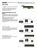
PREPARATION
INSTALLATION MUST BE PERFORMED BY AN EXPERT QUALIFIED PERSONNEL AND IN FULL COMPLIANCE WITH
CURRENT REGULATIONS. Gate must be constructed and installed according to ASTM F2200 standards.
Before installation, perform the following:
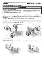
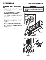
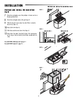
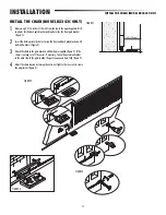
1
Make sure that the gate is stable, and that the castors are in good working order and properly greased.
2
The ground rack must be well secured to the ground, entirely above the surface and free of any irregularities that may obstruct the gate’s movement.
3
The upper guide rails must not create any friction.
4
Make sure that there is a closing and an opening endstops.
5
Make sure that the operator is attached to a solid surface and protected from any impacts;
6
Make sure you have a suitable omnipolar cut-off device with contacts more than 1/32” (3 mm) apart, and independent (sectioned off) power supply;
7
Check that any connections inside the container (that provide continuity to the safety circuit) are fitted with additional insulation compared to other internal live parts;
8
Make sure you have suitable tubing and conduits for the electrical cables to pass through and be protected against mechanical damage.
SITE PREPARATION
• Drill and Drill Bits
• Hack Saw
• Welder
• Tape Measure
• Pliers
• Open End Wrenches
• Screwdrivers
• Shears
• Level
• C-Clamps (Model BX243R Only)
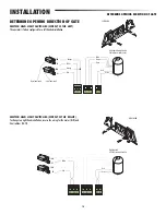
CONNECTION/DEVICE
AMERICAN WIRE GAUGE
(AWG)
WIRE LENGTH
Control panel power supply
120V
14AWG
3 ft. up to 100 ft.
Safety and control
devices
20AWG
3 ft. up to 100 ft.
NOTE:
If the length of the wire differs from that specified in the table, then you
must determine the proper wire gauge based on the actual power draw of the
devices connected and the local electrical codes. For connections that require several,
sequential loads, the sizes provided in the table must be re-evaluated based on
actual power draw and distances. When connecting products that are not specified in
this manual, refer to the instructions provided with said products.
NOTE:
Use copper conductors only.
WIRING CHART
Always check first for local and national electrical codes.


