


14
INSTALLATION
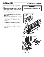
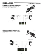
INSTALL THE OPERATOR (MODEL BX243R ONLY)
INSTALL THE OPERATOR (MODEL BX243R
ONLY)
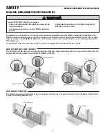
1
Release the operator by pulling the release lever (refer to page 15).
2
Rest the rack on the gearmotor pinion (Figure 1).
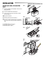
3
To assemble the rack modules, use an excess piece of rack and place it under
the joint. Secure the rack pieces with two C-clamps (Figure 1B).
4
Weld the rack to the gate along its entire length (Figure 1C).
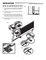
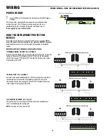
5
Open and close the gate manually and register the rack to pinion distance
using the levelling feet (for vertical adjustment) and the slotted holes (for
horizontal adjustment) (Figure 2).
6
Secure the operator using the nuts and washers (Figure 3).
7
Secure the cover with a screw on each side (Figure 3).
Rack
FIGURE 1A
FIGURE 1C
FIGURE 1B
FIGURE 2
FIGURE 3
Pinion
Coupling Distance
(1/32-5/64")


