background image

www. came.com

www. came.com

CAME Cancelli Automatici S.p.a.

CAME Cancelli Automatici S.p.a.

Via Martiri Della Libertà, 15

31030 Dosson Di Casier 

 Dosson Di Casier (Tv)

 (+39) 0422 4940 

 (+39) 0422 4941

Assistenza Tecnica/Numero Verde 800 295830

Assistenza Tecnica/Numero Verde 800 295830

IT 

• Per ogni ulteriore informazione su azienda, prodotti e assistenza nella vostra lingua:

EN 

• For any further information on company, products and assistance in your language:

FR 

• Pour toute autre information sur la société, les produits et l’assistance dans votre langue :

DE 

• Weitere Infos über Unternehmen, Produkte und Kundendienst bei:

ES 

• Por cualquier información sobre la empresa, los productos y asistencia en su idioma:

NL 

• Voor meer informatie over het bedrijf, de producten en hulp in uw eigen taal:

PT 

• Para toda e qualquer informação acerca da empresa, de produtos e assistência técnica, em sua língua:

PL 

• Wszystkie inne informacje dotyczące fi rmy, produktów oraz usług i pomocy technicznej w Waszym języku znajdują się na stronie:

RU 

• Для получения дополнительной информации о компании, продукции и сервисной поддержке на вашем языке:

HU 

• A vállalatra, termékeire és a műszaki szervizre vonatkozó minden további információért az Ön nyelvén:

HR 

• Za sve dodatne informacije o poduzeću, proizvodima i tehničkoj podršci:

UK 

• Для отримання будь-якої іншої інформації про компанію, продукцію та технічну підтримку:

E

n

g

li

sh

En

g

li

sh

  - M

an

u

al

 c

od

e: 

11

9

B

T

8

5

11

9

B

T

8

5

 ve

r.


2

  04/

2

0

14 © C

A

M

E c

an

ce

lli

 auto

m

ati

ci

 s.p.a. 

Th

e d

ata a

n

d i

nf

or

m

ati

on r

ep

orte

d i

n th

is

 in

sta

lla

tio

n m

an

u

al

 a

re s

u

sc

ep

tib

le to c

h

an

g

e at a

ny ti

m

e a

n

d w

ith

ou

t o

b

lig

ati

on

 o

n C

A

M

E c

an

ce

lli

 auto

m

ati

ci

 s.p.a. to n

otify u

se

rs.

Содержание BX-P

Страница 1: ...INSTALLATION MANUAL BX P AUTOMATION FOR SLIDING GATES English EN 119BT85EN ...

Страница 2: ...e is no vegetation in the area of operation of the photocells and that there are no obstacles in the area of operation of the operator Do not allow children to play with the fixed command devices or in the gate s area of operation Keep any remote control devices i e transmitters or any control devices away from children as well to prevent the operator from being activated accidentally The operator ...

Страница 3: ...30 x 8 module 4 rack with fastening screws holes and supports 009 CCT Simple 1 2 chain 009 CGIU 1 2 chain joint Important Check that the safety equipment and accessories are CAME originals this is a guarantee that also makes the system easy to set up and upkeep 4 Description 2 1 Destination 1 Legend This symbol indicates sections to be read with particular care This symbol indicates sections conce...

Страница 4: ...any irregularities that may obstruct the gate s movement The upper guide rails must not create any friction Make sure that there is a closing and an opening endstops Make sure that the operator is attached to a solid surface and protected from any impacts Make sure you have a suitable omnipolar cut off device with contacts more than 3 mm apart and independent sectioned off power supply Check that ...

Страница 5: ...al loads the sizes given on the table must be re evaluated based on actual power draw and distances When connecting products that are not specified in this manual please follow the documentation provided with said products 5 3 Cable list and minimum thickness Connection Type of cable Length of cable 1 10 m Length of cable 10 20 m Length of cable 20 30 m Control panel power supply 230V FROR CEI 20 ...

Страница 6: ...xamples as the space for installing the ratiomotor and accessories varies according to obstructions It is thus up to the system installer to select the most suitable solution Shunt pit 5 5 Securing the plate and installing the assembly Conduits for electric cables Prepare the securing plate insert the bolts into the holes and lock them using the supplied nuts and washers Extract the preformed brac...

Страница 7: ...NGLISH To position the plate in relation to the rack please see the measurements on the diagram Fill the form box with cement and wait for at least 24 hours for it to solidify Remove the form box fill the pit around the cement block with soil Unbolt the nuts and washers from the bolts The securing plate must be clean perfectly aligned and with the bolt threads completely on the surface Insert the e...

Страница 8: ...e cable shafts Lift the gearmotor from the securing plate by about 5 to 10mm by using the threaded steel levelling feet to allow any later adjustments between the pinion and the rack The following illustrations for the securing the rack are just examples of applications It is up to the installer to choose the best solution Releasing the gearmotor see paragraph on manual release Rest the rack on th...

Страница 9: ...e finished secure the assembly using the nuts and washers Insert the cover after performing the adjustments and settings on the electronic card Levelling feet Slotted holes Rack Pinion vertical adjusting horizontal adjusting Rack Pinion Open and close the gate manually and register the pinion to rack distance using the threaded steel levelling feet for vertical adjusting and the slotted holes horiz...

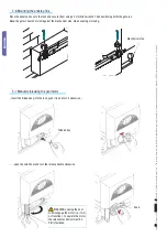
Страница 10: ...obed key into the lock push it in and turn it clockwise 5 6 Mounting the endstop fins Place the endstop fins onto the rack and secure them using a 3 mm Allen wrench Their positioning limits the gate run Note the gate schould not slam against the mechanical stop when opening or closing Mechanical stop Trilobed key Knob open the small door and turn the release handle clockwise WARNING opening the doo...

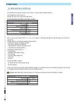
Страница 11: ...ts The card provides and controls the following optional functions automatic closing after an opening command pre flashing of the movement indicator obstacle detection with gate stopped at any point constant check of photocell operation The definable command modes are opening closing maintained action opening closing partial opening reopening during closing phase partial stop total stop The apposite...

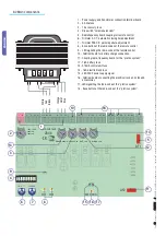
Страница 12: ...funzioni 5 Radiofrequency board coupling for remote control 6 Trimmer A C T automatic closing time adjustment 7 Trimmer PAR OP partial aperture adjustment 8 Save button of the radio codes of the remote control 9 LED signalling the radio code of the remote control 10 Terminal board for battery charge connection 11 Coupling radio frequency board for the pratico system 12 1 6A battery fuse 13 315mA c...

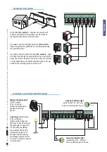
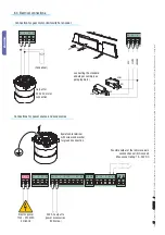
Страница 13: ...e leaf by pressing the button or turning the key on the selector the gate leaf inverts its direction of motion or stops depending on the chosen selection made on the dip switches see selecting functions dips 2 and 3 Movement flashing light Contact output 230V 25W max Flashes during the gate s opening and closing phases Connections to warning and illumination devices Cycle lamp contact rating 230V 6...

Страница 14: ...ENGLISH 6 3 Electrical connections Connection for gear motor limit switch or encoder Output for 230V AC motor connection RED ORANGE WHITE Eyelet cable terminal with screw and washer for ground connection Connections for power source and accessories Electric power 120V 230W AC 50 60 Hz 24V AC output to power accessories 20W max Condenser Possible output of the radio receiver s second channel N O so...

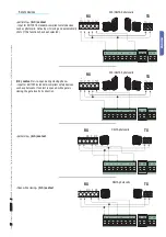
Страница 15: ...vices partial stop N C contact Input for EN 12978 standard compliant safety devices such as photocells Gate stops if moving and automatically shuts if this functions has been selected N C contact for re open during closing phase Input for EN 12978 standard compliant safety devices such as photocells If contact is opened while gate is closing the gate inverts its direction Open while closing N C co...

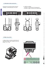
Страница 16: ... s p a to notify users ENGLISH 6 5 Motor torque limiter To change the torque move the faston identified by the black wire connected to the CT terminal to one of four positions 1 min 4 max 6 4 Gearmotor end stop connection Gearmotor end stop assembly already connected for installation on the left hand side seen from inside For right hand installation reverse FA FC of the end stops on the terminal bo...

Страница 17: ...unting does not start after partial opening con trimmer del A C T set to the maximum setting the closing time is fixed at 8 seconds after partial opening 1 ON Automatic closing The automatic closing timer is automatically activated at the end of the opening cycle The preset adjustable automatic closing time is automatically interrupted by the activation of any safety system and is deactivated after...

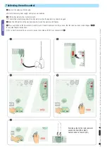
Страница 18: ...ation manual are susceptible to change at any time and without obligation on CAME cancelli automatici s p a to notify users ENGLISH 7 Activating the radio control Possible output of the radio receiver s second channel NO contact Contact rated for 5A 24V DC Connect the antenna s RG58 cable Cut off the main power supply and remove any batteries Fit the AF board onto the electronic board The electron...

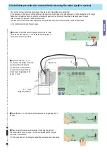
Страница 19: ... to be changed repeat the sequence described above Insert the terminal connected to the battery to the free coupling of the motherboard The board must be battery powered for saving procedures Check the LED signalling 230V power is off Electric lock 8 Installation procedure for automatically releasing the motor pratico system The pratico system automatically releases the automation through the radi...

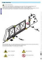
Страница 20: ...roneous or negligent uses Avoid working close to the hinges or other moving mechanical parts Stay out of the opening closing arc when operator is in motion Do not exercise force against the motion of the operator as this could result in potentially dangerous situations Do not allow children to play or loiter within the opening closing arc of the operator Keep remote controls and any other command ...

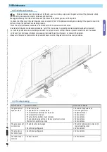
Страница 21: ...ble accidents due to gate movement To clean the photocells use a water dampened cloth Do not use solvents or other chemical products which may ruin the devices In the event of any strange vibrations or squeaking lubricate the joints with grease as shown in the diagram Make sure there are no plants within the photocell s beam and that the gate motion is free of any obstacles 10 2 Trouble shooting M...

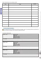
Страница 22: ...__________ __________________________________________________________________________________________________ __________________________________________________________________________________________________ Installer s stamp Operator name Date of job Technician s signature Requester s signature Job performed _______________________________________________________________________________________ ...

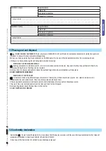
Страница 23: ...ed at authorised firms Other components electrical circuit board remote control batteries etc may contain hazardous waste They must thus be removed and turned in to licensed firms for their disposal Before acting always check the local laws on the matter DO NOT DISPOSE OF IN NATURE 11 Phasing out and disposal 12 Conformity declaration Installer s stamp Operator name Date of job Technician s signat...

Страница 24: ...e over het bedrijf de producten en hulp in uw eigen taal PT Para toda e qualquer informação acerca da empresa de produtos e assistência técnica em sua língua PL Wszystkie inne informacje dotyczące firmy produktów oraz usług i pomocy technicznej w Waszym języku znajdują się na stronie RU Для получения дополнительной информации о компании продукции и сервисной поддержке на вашем языке HU A vállalatra...

Отзывы: