


ENGLISH
p.
6
-
M
an
u
al
c
od
e:
11
9
B
F
0
3
11
9
B
F
0
3
ve
r.
2
04/2
0
14
© 0
9
/2
0
10 © C
A
M
E c
an
ce
lli
A
uto
m
ati
ci
S
.p.
A
. - T
h
e d
ata a
n
d i
nf
or
m
ati
on i
n th
is
m
an
u
al
m
ay b
e c
h
an
g
ed at a
ny ti
m
e a
n
d w
ith
ou
t o
b
lig
ati
on o
n th
e p
art of C
am
e C
an
ce
lli
A
uto
m
ati
ci
S
.p.a. to n
otify s
ai
d c
h
an
g
es.
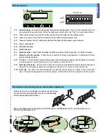
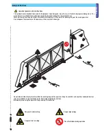
- Dig a pit at the end of the gate (see measurement quotas in drawing).
Set up the necessary corrugated tubing for connections coming from the junction pit.
N.B. the number of tubes depends on the type of installation and accessories used.
The following illustrations are just examples, in that, the space for securing the operator and accessories varies depending on
the overall measurements. It is up to the installer to choose the most suited solution.
Junction pit-box
Fastening the plate and fi tting the operator
Tubes for electrical cables
to pass through
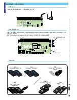
- Set up the anchoring plate, by threading the bolts and tightening them with the supplied nuts and washers. Extract the pre-shaped
brackets, using a screwdriver or pliers.
Position the plate above the grille. Warning! The tubes need to be threaded through the pre-set holes.
- Prepare a foundation box that is larger than the anchoring plate and fi t it into pit. The wooden form must protrude from the ground by
at least 50 cm.
Insert an iron grille into the wooden form to reinforce the concrete.


