


COM
NC
NC
COM
COM
NC
NC
COM
M N
L2T L1T
0 17
26
10 11 E1 1
2 3P 5
7
2 C1 C3 C7 C8 TS
+ E
-
FC FA
F
LINE FUSE
230V=1.6A-F
120V=3.15A-F
MOTOR FUSE
BX243=8A-F
BX246=10A-F
ACCESSORIES
FUSE
1.6A-F
C. BOARD
FUSE
1A-F
+
RUN S.
-
+
SLOW S.
-
+
RUN V.
-
+
SLOW V.
-
+
A.C.T.
-
+
PAR.OP.
-
ZN5 M1 ZN5U
CONTROL BOARD
PWR
1
C1
C3
C7
C8
ON
2
1
3
4
5
6
7
8
9 10
PROG.
M N
L2T L1T
L N
0 17
26
10 11 E1 1
2 3P 5
7
2 C1 C3 C7 C8 TS
+ E
-
FC FA
F
2
10
7
9
5
12
17
13
15
16
1
14
4
3
6
8
11
ENGLISH
p.
1
2
12
-
M
an
u
al
c
od
e:
11
9
B
F
0
3
11
9
B
F
0
3
ve
r.
2
04/2
0
14
© 0
9
/2
0
10 © C
A
M
E c
an
ce
lli
A
uto
m
ati
ci
S
.p.
A
. - T
h
e d
ata a
n
d i
nf
or
m
ati
on i
n th
is
m
an
u
al
m
ay b
e c
h
an
g
ed at a
ny ti
m
e a
n
d w
ith
ou
t o
b
lig
ati
on o
n th
e p
art of C
am
e C
an
ce
lli
A
uto
m
ati
ci
S
.p.a. to n
otify s
ai
d c
h
an
g
es.
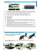
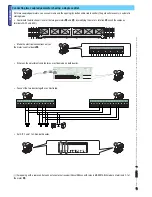
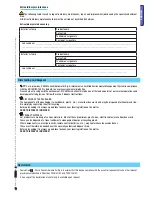
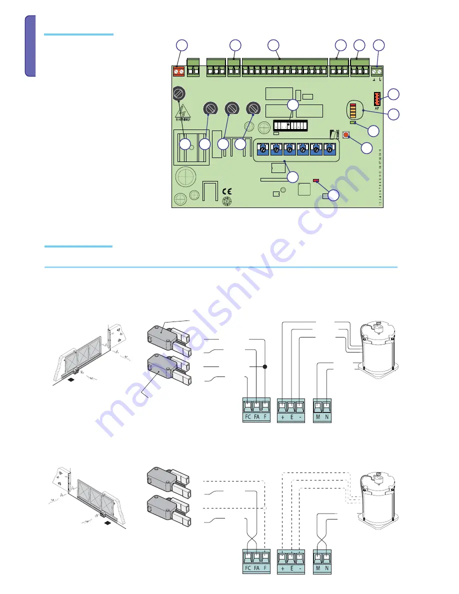
Electrical connections
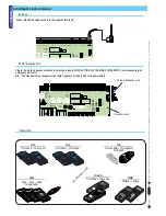
Gearmotor, endstop and encoder
1) Power source terminals
2) Endstop terminals
3) Motor terminals
4) Encoder terminals
5) Accessories fuse
6) Card fuse
7) radio-code memorisation button
8) Radio code notification LED light
9) 120V power supply LED warning-light
10) Control and notification LED warning-light
11) Features selector-switch
12) Radio-frequency card connector
13) Terminals for connecting the antenna
14) Terminals for connecting accessories and
command devices
15) Motor fuse
16) Line fuse
17) Adjustment Trimmer
Main component parts
Orange
Orange
White
White
Red
Red
Brown
Grey
Black
24 V (DC) motor
with encoder
Closing micro switch
To change installation side,
invert the gearmotor stages (M-N) and endstop ones (FA-FC)
Black
Black
Blue
Blue
Opening micro switch
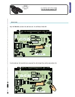
Description of electrical connections which are already established for left-hand installation


