CAME BKS22TGS Скачать руководство пользователя страница 19

Page 

3

 - Manual 

FA01157-EN

 - 09/2018 - © CAME S.p.A. - The contents of this manual may be changed, at any time, and without notice. - T

ranslation of the 

original instructions

GENERAL PRECAUTIONS FOR INSTALLERS

⚠ 

CAUTION! Important safety instructions.

Follow all of these instructions. Improper installation can cause serious bodily harm.

Before continuing, also read the general precautions for users.

Employ this product only for the use for which it was expressly made. Any other use is dangerous. Came S.p.A is not liable for any damage caused by 
improper, wrongful and unreasonable use • The product covered by this manual is defi ned in accordance with the Machinery Directive 2006/42/EC 
as a "partly completed machinery". The "partly completed machinery" is a whole that constitutes almost a machine, but that, by itself, is not able to 
guarantee a well-defi ned application. Partly completed machinery is only intended to be incorporated or assembled to other machines or other partly 
completed machinery or apparatus to constitute a machine governed by Directive 2006/42/EC. The fi nal installation must comply with the 2006/42/
EC (European directive) and with the current European reference standards. All procedures mentioned in this manual must be only be performed by 
skilled, qualifi ed technicians and in full compliance with current regulations. • The manufacturer declines any liability for using non-original products; 
which would result in warranty loss • Keep this manual inside the technical folder along with the manuals of all the other devices used for your au-
tomation system • Check that the temperature ranges given and those of the location match • Laying of cables, installation and testing must follow 
state-of-the-art procedures as dictated by applicable standards and laws • If the power-supply cable is damaged, it must be immediately replaced by 
the manufacturer or by an authorized technical assistance center, or in any case, by qualifi ed staff , to prevent any risk 
• Make sure the mains power supply is disconnected during all installation procedures • The product cannot automate any guided part that includes 
a pedestrian gate, unless the latter can be enabled only when the pedestrian gate is secured. • Make sure that people cannot be entrapped between 
the guided and fi xed parts, when the guided part is set in motion. • Before installing the operator, check that the guide part is in proper mechanical 
condition, that it is properly balanced and that it properly opens and closes: if any of these conditions are not met, do not continue before having 
met all safety requirements • Make sure that the gate is stable, that it opens and closes correctly and that the castors function properly and are well 
lubricated. • The ground rail must be well-fastened, entirely on the surface and are smooth and level so as not to obstruct the gate's movement • 
The rails of the upper tracks must not create friction • Make sure that opening and closing limiters are fi tted • Make sure that the operator is installed 
onto a sturdy surface that is protected from any collisions • Make sure that mechanical stops are already installed • If the dangerous moving parts of 
the operator are installed lower than 2.5 from the ground or from any other access level, fi t protections and/or signs to prevent hazardous situations.  
• Do not install the operator or onto elements that could yield and bend. If necessary, add suitable reinforcements to the anchoring points • Do not 
install door or gate leaves on tilted surfaces • Check that no lawn watering devices spray the operator with water from the bottom up • Any residual 
risks must be indicated clearly with proper signage affi  xed in visible areas. All of which must be explained to end users • Demarcate the entire site 
to prevent unauthorized personnel to enter; especially children and minors • Fit cautionary signs (such as the plate) wherever needed and in plain 
sight • Use suitable protections to prevent any mechanical hazards due to persons loitering within the operating range of the machinery (e.g. avoid 
crushing fi ngers between the rack and pinion) • The electrical cables must run through corresponding tubes, conduits and cable glands to ensure 
suitable protection against mechanical damage and they must not come into contact with parts that could heat up during use (such as motor and 
transformer). • Make sure you have set up a suitable dual pole cut off  device along the power supply that is compliant with the installation rules. It 
should completely cut off  the power supply according to category III surcharge conditions • Install all fi xed controls at 1.5 m from the ground, clearly 
visible, in view of the guided part but far away from moving parts. If there is a maintained action command, it must not be accessible to the public. • 
If necessary, to pass the collision force test use a suitable sensitive safety-edge (as indicated below in this manual). Install it properly and adjust as 
needed. • Before handing over to users, check that the system is compliant with the 2006/42/CE uniformed Machinery Directive and with its essential 
requirements. Make sure that the operator has been properly adjusted and that the safety and protection devices, and the manual release, are working 
properly • Make sure to hand over to the end user, all operating manuals for the products that make up the fi nal machinery.

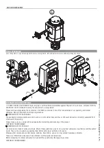
The next fi gure shows the main hazard points for people

.

Danger of high voltage.

Danger of crushing.

Danger of foot crushing.

Danger of hand entrapment.

Do not transit through during maneuvering.

Page 

3

 - Manual 

FA01157-EN

 - 09/2018 - © CAME S.p.A. - The contents of this manual may be changed, at any time, and without notice. - Original instructio

ns

Содержание BKS22TGS

Страница 1: ...zione per cancelli scorrevoli BKS22TGS MANUALE DI INSTALLAZIONE FA01157 IT Automazione per cancelli scorrevoli BKS22TGS MANUALE DI INSTALLAZIONE FA01157 IT IT Italiano EN English FR Fran ais RU P FA01...

Страница 2: ...2 3 1 2 3 1...

Страница 3: ...opra della super cie e priva di irregolarit che possano bloccare il movimento del cancello I binari della guida superiore non devono creare attrito Accertarsi della presenza di un necorsa di apertura...

Страница 4: ...progettato per motorizzare cancelli scorrevoli per uso condominiale o industriale TIPOLOGIA D IMPIEGO Modello BKS22TGS Lunghezza standard di riferimento parte scorrevole m 10 Peso massimo parte scorre...

Страница 5: ...canico 5 Piastra di fissaggio 6 Minuteria di fissaggio 7 Alette finecorsa IMPIANTO TIPO 1 Motoriduttore 2 Alette di finecorsa 3 Cremagliera 4 Selettore a chiave 5 Antenna e 6 Lampeggiatore 7 Fotocellu...

Страница 6: ...per il passaggio dei cavi elettrici garantendone la protezione contro il danneggiamento meccanico TIPO CAVI E SPESSORI MINIMI Collegamento lunghezza cavo 20 m 20 30 m Alimentazione quadro 230 400 V 4...

Страница 7: ...erire le viti nella piastra di fissaggio e bloccarle con i dadi Estrarre le zanche preformate con un cacciavite o una pinza Inserire la piastra nella griglia Attenzione I tubi devono passare attravers...

Страница 8: ...serire i cavi elettrici nei tubi fino a farli uscire di 600 mm circa Togliere la cassa matta e riempire di terra lo scavo attorno al blocco di cemento PREPARAZIONE DEL MOTORIDUTTORE Rimuovere il coper...

Страница 9: ...mettere eventuali regolazioni successive tra pignone e cremagliera FISSAGGIO DELLA CREMAGLIERA Se la cremagliera c gi procedere direttamente alla regolazione della distanza di accoppiamento pignone cr...

Страница 10: ...a distanza dell accoppiamento pignone cremagliera con i piedini filettati regolazione verticale e le asole regolazione orizzontale Questo permette di evitare che il peso del cancello gravi sul motorid...

Страница 11: ...necorsa di chiusura sulla cremagliera no a far scattare il micro molla e ssarla con i grani 20 mm 20 mm COLLEGAMENTI ELETTRICI Eseguire i collegamenti elettrici secondo le disposizioni vigenti Prima d...

Страница 12: ...a di protezione e far passare i cavi derivanti dal quadro esterno COLLEGAMENTO DEL MOTORIDUTTORE E DEL FINECORSA Collegamento del gruppo finecorsa standard VERDE ROSSO BIANCO Gruppo motoriduttore neco...

Страница 13: ...ulla morsettiera invertire le fasi U V del motore sulla morsettiera MODIFICHE SUI COLLEGAMENTI ELETTRICI PER EVENTUALE INSTALLAZIONE DEL MOTORIDUTTORE A DESTRA VERDE ROSSO BIANCO 230V AC 400V AC ARANC...

Страница 14: ...dell imballo cartone plastiche etc sono assimilabili ai rifiuti solidi urbani e possono essere smaltiti senza alcuna difficolt semplicemente effettuando la raccolta differenziata per il riciclaggio P...

Страница 15: ...scettibili di modifica in qualsiasi momento senza obbligo di preavviso Traduzione delle istruzioni originali Pag 15 Manuale FA01157 IT 09 2018 CAME S p A I contenuti del manuale sono da ritenersi susc...

Страница 16: ...CAME S p A I contenuti del manuale sono da ritenersi suscettibili di modifica in qualsiasi momento senza obbligo di preavviso Traduzione delle istruzioni originali Pag 16 Manuale FA01157 IT 09 2018 CA...

Страница 17: ...EN English FA01157 EN Sliding gate operator BKS22TGS INSTALLATION MANUAL...

Страница 18: ...2 3 1 2 3 1...

Страница 19: ...ust be well fastened entirely on the surface and are smooth and level so as not to obstruct the gate s movement The rails of the upper tracks must not create friction Make sure that opening and closin...

Страница 20: ...liding gates used in apartment blocks and industrial plants INTENDED USE Model BKS22TGS Standard reference length of the sliding part m 10 series Maximum weight of the sliding part kg 2 200 series Pin...

Страница 21: ...tor 4 Mechanical limit switch 5 Anchoring plate 6 Fastening hardware 7 Limit switch tabs STANDARD INSTALLATION 1 Gearmotor 2 Limit switch fins 3 Rack 4 Key switch selector 5 Antenna s 6 Flashing light...

Страница 22: ...ctric cables to pass through making sure they are protected from any mechanical damage CABLE TYPES AND MINIMUM THICKNESSES Connection cable length 20 m 20 30 m Control panel power supply 230 400 V 4G...

Страница 23: ...Fit the bolts into the anchoring plate and tighten them using the nuts Remove the pre shaped clamps using a screw driver or pliers Fit the plate into the iron cage Caution The tubes must run through...

Страница 24: ...m the bolts Fit the electric cables into the tubes so that they come out about 600 mm Remove the foundation frame and fill the hole with earth around the concrete block PREPARING THE GEARMOTOR Remove...

Страница 25: ...from the plate by turning the threaded feet to make room for further pinion and rack adjustments FASTENING THE RACK If the rack is already set up the next step should be to adjust the rack and pinion...

Страница 26: ...just the pinion rack coupling distance using the threaded feet vertical adjustment and the holes horizontal adjustment This prevents the gate s weight from bearing down on the gearmotor FASTENING THE...

Страница 27: ...g limit switch tab into the rack until the micro switch is activated spring and fasten it using the grub screws 20 mm 20 mm ELECTRICAL CONNECTIONS Connect all wires and cables in compliance with the l...

Страница 28: ...tive box and run through it the cables from the external panel CONNECTING THE GEARMOTOR AND THE LIMIT SWITCH Connection of the standard limit switch assembly GREEN RED WHITE Gearmotor limit switch ass...

Страница 29: ...h micro switch Opening limit switch micro switch Mechanical limit switch GREEN RED WHITE Thermal pad For installing on the right reverse the limit switch FA FC on the terminal board reverse the U V ph...

Страница 30: ...materials cardboard plastic and so on should be disposed of as solid household waste and simply separated from other waste for recycling Always make sure you comply with local laws before dismantling...

Страница 31: ...ontents of this manual may be changed at any time and without notice Translation of the original instructions Page 15 Manual FA01157 EN 09 2018 CAME S p A The contents of this manual may be changed at...

Страница 32: ...4941 Page 16 Manual FA01157 EN 09 2018 CAME S p A The contents of this manual may be changed at any time and without notice Translation of the original instructions Page 16 Manual FA01157 EN 09 2018 C...

Страница 33: ...Automatisme pour portails coulissants BKS22TGS MANUEL D INSTALLATION FR Fran ais FA01157 FR...

Страница 34: ...2 3 1 2 3 1...

Страница 35: ...sont en bon tat et bien lubri es Contr ler que le rail est solidement x au sol enti rement en surface et qu il ne pr sente aucune irr gularit pouvant emp cher le mouvement du portail Contr ler que les...

Страница 36: ...jusqu 2200 kg et 23 m de longueur UTILISATION PR VUE Le motor ducteur a t con u pour motoriser des portails coulissants usage collectif ou industriel TYPE D UTILISATION Mod le BKS22TGS Longueur standa...

Страница 37: ...orme EN 60335 2 103 DESCRIPTION DES PARTIES 1 Couvercle 2 Couvercle frontal 3 Motor ducteur 4 Fin de course m canique 5 Plaque de fixation 6 l ments de fixation 7 Ailettes fin de course INSTALLATION S...

Страница 38: ...la surface de fixation est bien solide pr voir des tuyaux et des conduites pour le passage des c bles lectriques afin de les prot ger contre la d t rioration m canique TYPE DE C BLES ET PAISSEURS MINI...

Страница 39: ...rille en fer dans le coffrage pour couler le ciment Introduire les vis dans la plaque de fixation et les bloquer l aide des crous Extraire les agrafes pr form es l aide d un tournevis ou d une pince I...

Страница 40: ...moment et sans aucun pr avis Instructions originales Enlever les crous des vis Introduire les c bles lectriques dans les gaines jusqu ce qu ils sortent d environ 600 mm Enlever le coffrage et remplir...

Страница 41: ...ormateur etc Soulever le motor ducteur de 5 10 mm de la plaque en intervenant sur les pieds filet s afin de permettre par la suite les ventuels r glages entre pignon et cr maill re FIXATION DE LA CR M...

Страница 42: ...ACCOUPLEMENT PIGNON CR MAILL RE Ouvrir et fermer le portail manuellement et r gler la distance de l accouplement pignon cr maill re l aide des pieds filet s r glage vertical et des fentes r glage hori...

Страница 43: ...ssort En phase de fermeture fermer le portail en ler l ailette de n de course de fermeture sur la cr maill re jusqu au d clic du micro interrupteur ressort et la xer l aide des goujons 20 mm 20 mm BRA...

Страница 44: ...is Instructions originales Ouvrir le bo tier de protection Percer le bo tier de protection et faire passer les c bles provenant de l armoire externe CONNEXION DU MOTOR DUCTEUR ET DES BUT ES DE FIN DE...

Страница 45: ...Pour une ventuelle installation droite inverser FA FC des ns de course sur le bornier inverser les phases U V du moteur sur le bornier MODIFICATIONS SUR LES BRANCHEMENTS LECTRIQUES POUR UNE VENTUELLE...

Страница 46: ...ndications en mati re d limination LIMINATION DE L EMBALLAGE Les composants de l emballage carton plastiques etc sont assimilables aux d chets urbains solides et peuvent tre limin s sans aucune diffic...

Страница 47: ...nstructions originales Page 15 Manuel FA01157 FR 09 2018 CAME S p A Le contenu de ce manuel est susceptible de subir des modifications tout moment et sans aucun pr avis Instructions originales Page 15...

Страница 48: ...FR 09 2018 CAME S p A Le contenu de ce manuel est susceptible de subir des modifications tout moment et sans aucun pr avis Traduction des instructions originales Page 16 Manuel FA01157 FR 09 2018 CAM...

Страница 49: ...BKS22TGS RU FA01157 RU...

Страница 50: ...2 3 1 2 3 1...

Страница 51: ...3 FA01157 RU 09 2018 CAME S p A CAME S p A 2006 42 CE 2006 42 CE 2006 42 CE 2 5 III 1 5 2006 42 CE 3 FA01157 RU 09 2018 CAME S p A O...

Страница 52: ...43 326 22 max 359 5 105 106 170 262 4 FA01157 RU 09 2018 CAME S p A 2200 23 BKS22TGS 10 2 200 6 BKS22TGS IP 44 50 60 230 400 50 60 230 400 520 1650 10 5 C 20 55 I C 150 21 4 FA01157 RU 09 2018 CAME S...

Страница 53: ...7 7 1 1 2 2 3 3 4 4 5 FA01157 RU 09 2018 CAME S p A 14 17 20 C EN 60335 2 103 1 2 3 4 5 6 7 1 2 3 4 5 6 7 8 9 10 11 002ZT6 002ZT6C 001B4353 009CCT 1 2 009CGIU 1 2 001R001 5 FA01157 RU 09 2018 CAME S p...

Страница 54: ...0 6 FA01157 RU 09 2018 CAME S p A 20 20 30 230 400 4G x 2 5 2 4G x 4 2 230 400 4G x 1 5 2 4G x 2 5 2 2 x 1 5 2 2 x 0 5 2 TX 2 x 0 5 2 RX 4 x 0 5 2 3 x 1 2 RG58 5 CEI EN 60204 1 40 6 FA01157 RU 09 201...

Страница 55: ...50 2 1 UNI 5739 12 X 70 M12 84 105 7 FA01157 RU 09 2018 CAME S p A 50 24 7 FA01157 RU 09 2018 CAME S p A O...

Страница 56: ...8 FA01157 RU 09 2018 CAME S p A 600 8 FA01157 RU 09 2018 CAME S p A O...

Страница 57: ...5 10 9 FA01157 RU 09 2018 CAME S p A 5 10 9 FA01157 RU 09 2018 CAME S p A O...

Страница 58: ...1 2 10 FA01157 RU 09 2018 CAME S p A 10 FA01157 RU 09 2018 CAME S p A O...

Страница 59: ...1 2 2 2 1 11 FA01157 RU 09 2018 CAME S p A 20 20 11 FA01157 RU 09 2018 CAME S p A O...

Страница 60: ...U V W E1 EX ZT6 ZT6C W2 U2 V2 W1 U1 V1 W2 U2 V2 W1 U1 V1 Y O F A F C FC FA F 12 FA01157 RU 09 2018 CAME S p A 230 230 400 12 FA01157 RU 09 2018 CAME S p A O...

Страница 61: ...U V W E1 EX FC FA F ZT6 ZT6C W2 U2 V2 W1 U1 V1 W2 U2 V2 W1 U1 V1 Y O F A F C FC FA O 13 FA01157 RU 09 2018 CAME S p A FA FC U V 230 400 13 FA01157 RU 09 2018 CAME S p A O...

Страница 62: ...14 FA01157 RU 09 2018 CAME S p A CAME S p A UNI EN ISO 14001 14 FA01157 RU 09 2018 CAME S p A O...

Страница 63: ...15 FA01157 RU 09 2018 CAME S p A 15 FA01157 RU 09 2018 CAME S p A O...

Страница 64: ...CAME S p A Via Martiri Della Libert 15 31030 Dosson di Casier Treviso Italy tel 39 0422 4940 fax 39 0422 4941 16 FA01157 RU 09 2018 CAME S p A 16 FA01157 RU 09 2018 CAME S p A O...

Отзывы: