


500
340
400
r 40
p.
55
- M
an
u
al
c
od
e:
F
A
0
0
5
8
3
-E
N
FA
0
0
5
8
3
-E
N
v.
1
1
10
/2
0
1
6 - © C
am
e S
.p.
A
. T
h
e c
onte
nts of th
is
m
an
u
al
m
ay b
e c
h
an
g
ed at a
ny ti
m
e w
ith
ou
t p
rio
r n
oti
ce
.
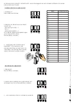
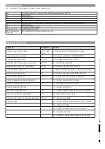
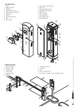
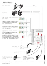
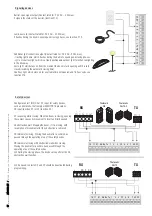
Cable types and minimum thicknesses
Connection
Cable type
Cable length
1 < 15 m
Cable length
15 < 30 m
Power supply to the 230 V AC control panel (1P+N+PE)
H05RN-F
3G x 1.5 mm
2
3G x 2.5 mm
2
Photocell transmitters
FROR CEI 20-22
CEI EN
50267-2-1
2 x 0.5 mm
2
Photocell receivers
4 x 0.5 mm
2
Command and safety device
2 x 0.5 mm
2
Antenna
RG58
max 10 m
If cable lengths diff er from those specifi ed in the table, establish the cable sections depending on the actual power draw of the connected
devices and according to the provisions of regulation CEI EN 60204-1.
For multiple, sequential loads along the same line, the dimensions on the table need to be recalculated according to the actual power draw and
distances. For connecting products that are not contemplated in this manual, see the literature accompanying said products
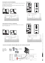
GENERAL INSTALLATION INDICATIONS
⚠
Only skilled, qualified staff must install this product.
Important! Suing CAME original control and safety devices and accessories ensures easy system installation and maintenance.
Preliminary checks
⚠
Before beginning, do the following:
• make sure the plate is anchored to a solid spot;
• make sure you have set up a suitable dual pole cut off device along the power supply that is compliant with the installation rules. It should
completely cut off the power supply according to category III surcharge conditions (that is, with minimum contact openings of 3 mm);
• Make sure that any connections inside the casing (ones that ensure continuity to the protection circuit) are fitted with additional insulation
with respect to those of other electrical parts inside;
• set up suitable tubes and conduits for the electric cables to pass through, making sure they are protected from any mechanical damage.
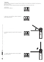
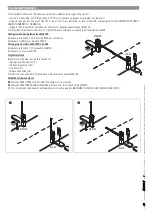
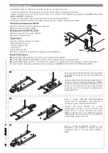
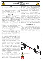
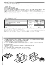
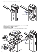
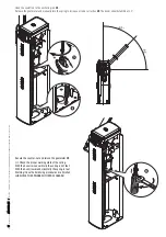
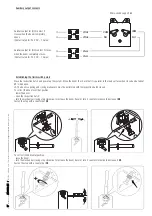
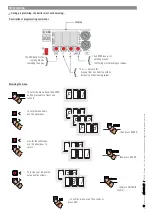
INSTALLATION
⚠
The following illustrations are mere examples. Consider that the space available where to fit the barrier and accessories will vary depending
on the area where it is installed. It is up to the installer to find the most suitable solution.
⚠
Warning! Warning! Use hoisting equipment to transport and position the barrier.
During the set up and installing stages the barrier could be unstable and tip over. So, be careful to not lean on it until it is completely fastened.
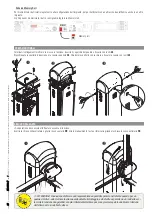
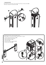
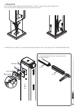
Preparing the fastening plate.
⚠
If the flooring does not allow for a sturdy fastening of the entry unit, you will have to set up a cement slab.
Dig a hole for the foundation frame.
Set up the corrugated tubes needed for making the connections coming out of the junction pit.
The number of tubes depends on the type of system and the accessories you are going to fit.
Содержание 001G4040EZT
Страница 1: ...English EN Русский RU Italiano IT Français FR FA00583M04 BARRIERE AUTOMATICHE ...
Страница 33: ...English EN INSTALLATION MANUAL G4040EZT AUTOMATIC BARRIERS FA00583 EN ...
Страница 65: ...Français FR MANUEL D INSTALLATION G4040EZT BARRIÈRES AUTOMATIQUES FA00583 FR ...
Страница 97: ...Русский RU ИНСТРУКЦИЯ ПО МОНТАЖУ G4040EZT АВТОМАТИЧЕСКИЕ ДОРОЖНЫЕ ШЛАГБАУМЫ FA00583 RU ...


