740C SERVICE MANUAL
TABLE OF CONTENTS
Safety Precautions & Important Notes
3
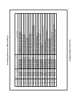
Exploded
Diagram 4
Exploded Diagram Parts List
5
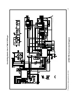
Front
Panel
Circuit
Diagram
6
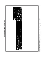
Front Panel Board Layout (Top Side)
7
Front Panel Board Layout (Bottom Side)
8
Front
Panel
PCB
BOM
9
Servo
Circuit
Diagram
10
Servo Board Layout (Top Side)
11
Servo Board Layout (Bottom Side)
12
Servo Assembly PCB BOM
13-15
DAC Circuit Diagram (Supply & Connectors)
16
DAC
Circuit
Diagram
(SPDIF
–
RS232)
17
DAC Circuit Diagram (Flash Connector & Mute)
18
DAC
Circuit
Diagram
(DSP)
19
DAC
Circuit
Diagram
(Analogue
Stage)
20
DAC Board Layout (Top Side)
21
DAC
Board
Layout
(Bottom
Side)
22
DAC
Assembly
PCB
BOM
23-25
Mains
Circuit
Diagram
26
Mains
Board
Layout
(Top
Side)
27
Mains
Board
Layout
(Bottom
Side)
28
Mains
PCB
BOM
29
IC
Pin
Layout
Details
30-38
2
Содержание Azur 740C
Страница 4: ...Cambridge Audio Azur 740C CD Player Exploded Diagram To enhance viewing please print to A3 4 ...
Страница 30: ...Cambridge Audio Azur 740C CD Player IC Pin Layout Details TA2153FN Servo PCB U1 TC9462FG Servo PCB U2 30 ...
Страница 34: ...4011 DAC PCB U3 APRX179AT DAC PCB U4 U5 74VHC14 DAC PCB U6 U15 74VHC153 DAC PCB U7 74HCT153 DAC PCB U9 34 ...
Страница 36: ...7815 DAC PCB U14 U22 U49 U51 7915 DAC PCB U16 U24 LM1117T 3 3 DAC PCB U18 U26 36 ...


