Chapter 3: System planning
146
l
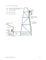
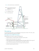
The drop cable shield must be grounded at the bottom of the tower, near the vertical to horizontal
transition point. This ground cable must be bonded to the tower or tower ground bus bar (TGB), if
installed.
l
If the tower is greater than 61 m (200 ft) in height, the drop cable shield must be grounded at the
tower midpoint, and at additional points as necessary to reduce the distance between ground
cables to 61 m (200 ft) or less.
l
In high lightning-prone geographical areas, the drop cable shield must be grounded at spacing
between 15 to 22 m (50 to 75 ft). This is especially important on towers taller than 45 m (150 ft).
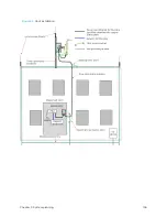
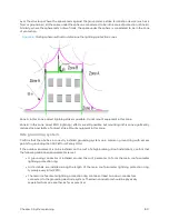
For roof installations (Roof installation), use the following additional criteria:
l
The drop cable shield must be bonded to the building grounding system at its top entry point
(usually on the roof).
l
The drop cable shield must be bonded to the building grounding system at the entry point to the
equipment room.
Lig ht ning Pr ot ect ion Unit ( LPU) locat ion
Find a location for the bottom LPU that meets the following requirements:
l
The bottom LPU can be connected to the drop cable from the ODU.
l
The bottom LPU is within 600 mm (24 in) of the point at which the drop cable enters the building,
enclosure or equipment room within a larger building.
l
The bottom LPU can be bonded to the grounding system.
Rad io Freq uency p lanning
This section describes how to plan 450 Platform Family links to conform to analysis of spectrum and the
regulatory restrictions that apply in the country of operation.
Reg ulat or y lim it s
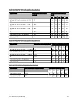
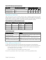
Many countries impose EIRP limits (Allowed EIRP) on products operating in the bands used by the 450
Platform Family.
Refer to Equipment Disposal in Configuratgion Guide to determine what the maximum transmitted power
and EIRP for PMP/PTP 450 Platform that can be used in each of countries and frequency band.
Caution
It is the responsibility of the user to ensure that the PMP/PTP ODU is operated in
accordance with local regulatory limits.
Note
Contact the applicable radio regulator to find out if registration of the
PMP/PTP 450 Platform link is required.
Содержание PMP 450 Series
Страница 92: ...Chapter 2 System hardware 92 Figure 29 MicroPoP Omni antenna implementation pattern Vertical...
Страница 134: ...Chapter 3 System planning 134 Figure 51 Mast or tower installation...
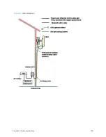
Страница 135: ...Chapter 3 System planning 135 Figure 52 Wall installation...
Страница 136: ...Chapter 3 System planning 136 Figure 53 Roof installation...
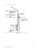
Страница 137: ...Chapter 3 System planning 137 Figure 54 GPS receiver wall installation...
Страница 158: ...Chapter 3 System planning 158 Figure 61 cnMedusa Antenna...
Страница 258: ...Chapter 5 Installation 258 Figure 123 Yagi antenna alignment horizontally Figure 124 Yagi antenna alignment upward tilt...


