CAMAG TLC SCANNER 4 Скачать руководство пользователя страница 5


TLC Scanner 4 


Instruction Manual, June 2018 

Page 4 


The instrument contains highly sophisticated electronics and 
optical parts. It may be operated only in a non-condensing at-
mosphere in the temperature range outlined in the chapter 
"Technical Data". Before installation and use, the instrument 
should be acclimated properly 


Use a damp lint free cloth for cleaning the instrument surface. 
Do not employ aggressive detergents 


Protect yourself and the instrument from electrostatic shock 
which can cause damage to the electronic parts 


Only authorized personnel may open the instrument. Service 
and  repair is only to be performed by trained specialists. Use 
spare parts and consumables supplied by CAMAG only. The 
warranty is voided if parts from other sources are used. Check 
the service manual before you start service to reduce product-
specific risks 


The power cord has to be removed before the instrument is 
opened. It is not permitted to work on an instrument that has 
been opened and is connected to the power supply 


Use only the original, with the instrument delivered power cord 
type 


If the instrument is found to be defective, it must be switched 
off and steps must be taken to ensure that it cannot be switched 
on by mistake 


If liquids penetrate the inside of the instrument, the power has 
to be disconnected immediately. Small amounts of liquid can be 
wiped off and/or dried with a  of a blow dryer, with larger 
amounts of liquid a service technician has to be called. A test of 
functionality has to be performed in all cases 


Carry out all safety checks and the preventive maintenance as 
recommended by the manufacturer in order to assure your per-
sonal safety and the full functionality of the instrument. Have 
an authorized service specialist perform any service not de-
scribed by this manual 


See original manufacturers' manuals for further safety data on 
third party equipment supplied with the system 


Lift/move/transport the system with the necessary care and with 
sufficient manpower (install the transport security devices if ap-
plicable, transport it only in the original packaging) 


The safety of any system incorporate with the equipment is the 
responsibility of the assembler of the system 

Содержание TLC SCANNER 4

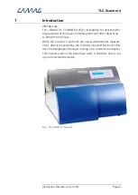
Страница 1: ...INSTRUCTION MANUAL TLC SCANNER 4...

Страница 2: ...The keypad and display 11 4 1 ILLUM Compartment illumination 11 4 2 LOAD Table in load position 11 4 3 Arrow keys Move stage 12 4 4 RESET Warm start of the Scanner 4 12 5 Maintenance 13 5 1 Replacing...

Страница 3: ...r chromatograms and other objects up to 200x200 mm in size While the Scanner 4 performs the actual densitometric measure ment data is processed by the CAMAG visionCATS winCATS Pla nar Chromatography M...

Страница 4: ...nstrument If the instrument is used in a manner not specified in this man ual the protection provided by the equipment may be impaired Attention For safety reasons the instrument may only be used for...

Страница 5: ...he power supply Use only the original with the instrument delivered power cord type If the instrument is found to be defective it must be switched off and steps must be taken to ensure that it cannot...

Страница 6: ...es and UV absorbent gloves must be worn To ensure sufficient cooling the ventilation holes of the instru ment must never be obstructed 2 Parts information Parts supplied Part No Quantity Description 1...

Страница 7: ...the instrument Operating temperature The temperature should be within a range of 20 to 35 C and free of significant variations Humidity Humidity and temperature conditions must not cause condensation...

Страница 8: ...noise reduction unit is in the same power line 3 2 Conditions for the installation Check the following requirements before installing the instrument Power supply and ground Line voltage 115 or 230VAC...

Страница 9: ...pply 3 Fig 3 The power connection Before connecting the Scanner 4 to the wall outlet check whether the voltage selector switch 1 is set in the appropriate position matching the mains power voltage of...

Страница 10: ...or housing can be flushed with nitrogen Proceed as follows Remove the nut from the tubing nipple Fig 3 3 Push the connecting tubing of the nitrogen supply 3x4 3mm pneumatic tubing through the back of...

Страница 11: ...a 2 mm offset in Y direction When mainly TLC HPTLC foils are used replace the standard plate stopper 2 with the special foil holder 115 6217 1 Fig 6 To replace the standard plate stopper remove the tw...

Страница 12: ...ss the ILLUM key to ignite the compartment illumination The Scanner 4 automatically moves the monochromator to 546nm and ignites the Tungsten lamp in order to make the slit visible The com partment il...

Страница 13: ...ion of the arrow The table will start slowly and acceler ates if the key remains pressed The current position of the table in X and Y is displayed live A diagonal movement pressing two keys is not pos...

Страница 14: ...parts on the instrument make sure the instrument is disconected from the mains 5 1 Replacing the lamps Exchange lamps only when they have cooled down properly Switch OFF the Scanner 4 and disconnect...

Страница 15: ...pressing the LOAD POS key The following will now happen automatically The position of the lamp will be optimized in the ray path The emitted light energy of the new lamp will be measured and saved fo...

Страница 16: ...carefully in the op posite manner 3 Fig 9 and Fig 10 Be careful Do not damage the filter holder Rotate the fluorescent tube about 90 degrees and remove it ac cording to Fig 11 Mount a new tube and ma...

Страница 17: ...TLC Scanner 4 Instruction Manual June 2018 Page 16 Fig 10 Taking out the PM cover Fig 11 Replacing the compartment illumination lamp...

Страница 18: ...nterval if applicable In addition it identifies con sumable parts with the respective replacement cycle Maintenance interval Mainte nance 12 Months IQ OQ 12 Months Consumable parts Part No Description...

Страница 19: ...eans of the key Use the keys and or to select the desired Baud rate Press or to save the new value The new Baud rate is now valid recommended 19 200 baud The new Baud rate will be recognized automatic...

Страница 20: ...much as 2 minutes to run this task In the USER Dialog advance to the function NEW W LAMP by means of the key Use the key to select the Tungsten lamp optimizing function the message CONFIRM LOAD POS a...

Страница 21: ...lectable 5 100 mm s return 150 mm s Power supply 115V and 230V 50 60 Hz Power consumption max 180 W Tungsten and Mercury lamps ON Nitrogen Consumption at approx 0 5 bar 6 L min Interface RS 232 port f...

Страница 22: ......

Страница 23: ..._____________________________________________________________ __________________________________________________________________________________ _______________________________________________________...

Страница 24: ..._____________________________________________________________ __________________________________________________________________________________ _______________________________________________________...

Страница 25: ..._____________________________________________________________ __________________________________________________________________________________ _______________________________________________________...

Отзывы: