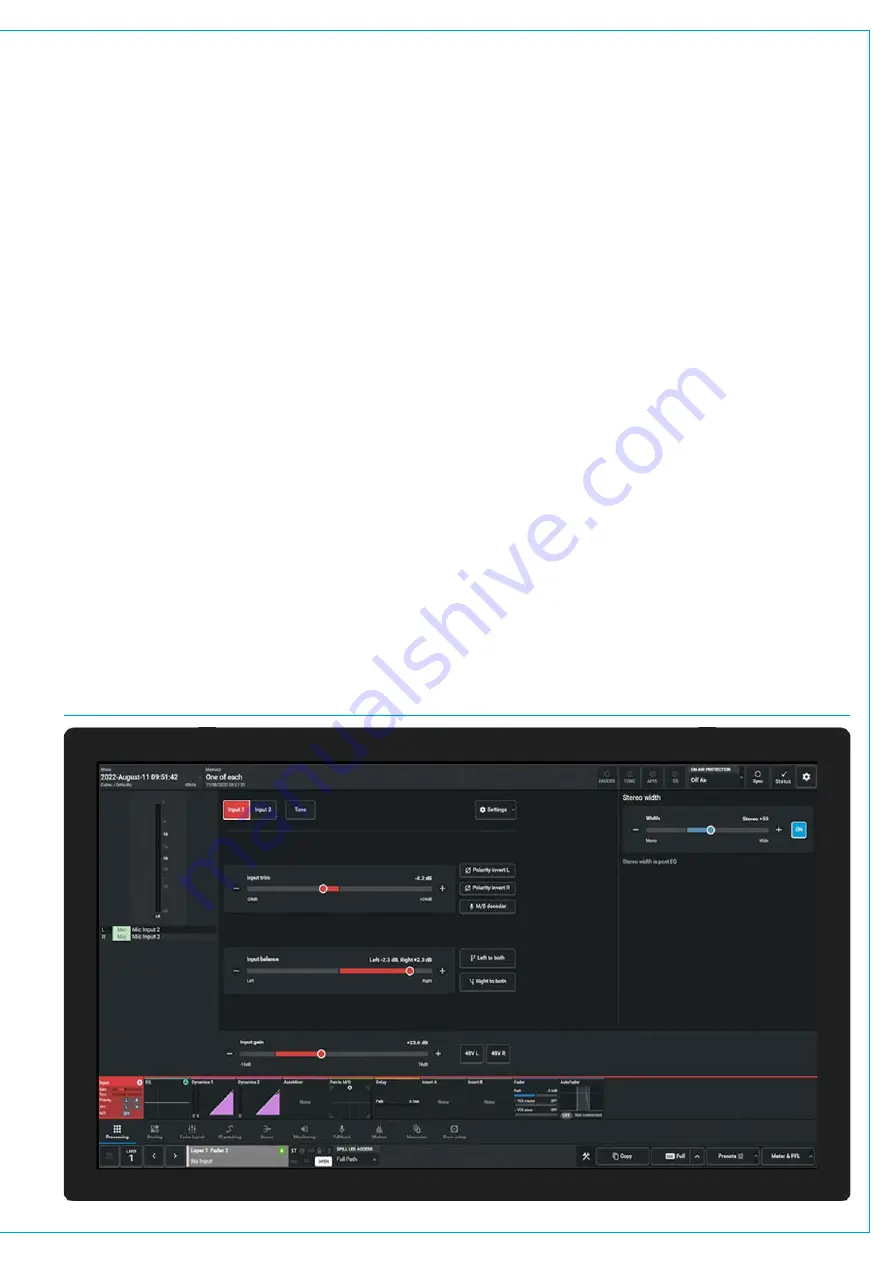
MU6572 TOUCHSCREEN PANEL DETAIL
Console Touch UI Application
Once the Touch UI application has started,
and the user is logged in if not already
done so via the Login screen, the menu
pages can be selected by tapping on the
menu icons across the bottom of the GUI.
The main purpose of the TFT touchscreen
panel on the console surface is to run the
Console Touch UI application, providing
access to various console options. The
Touch UI application is launched when
the console is powered up. It interacts
with the Modes & Layers row of the fader
panels providing an alternate method
of controlling the console functions and
displaying the relevant settings.
The image below shows the layout of the
Touch UI application. Along the bottom
of the application is the main menu which
contains buttons for each of the main
sections of the application. In this manual,
the instruction to go to the
Processing
mode, it is the equivalent of saying:
‘
Touch the Processing button in the
Touch UI application main menu’
.
Once a certain mode has been selected,
a list of related sub-menu buttons options
will appear just above the main menu row.
Touching one of these buttons will
update the main application to display
the relevant screen. When for example
instructed to go to a certain sub-menu
screen, such as
>Processing>Input
it is
referring to touching the relevant button
on this list, along the bottom edge of the
screen. This has the same action as if the
Processing and Input buttons had been
pressed on the Modes & Layers row of a
standard fader panel
The touchscreen display below is selected
to show the
Processing>Input
for the
path shown bottom left of the screen.
Layer 1 Fader 2A, a stereo channel input.
The upper half of the screen shows all
the parameter controls associated with
the input section of that channel path
including metering data and input source
identification on the left, Input 1/2 and
Tone selections top middle, Input trim,
Input balance (if stereo), Input Gain
(if it has an analogue mic/line input) and
various signal conditioning buttons. To
the right of this is shown the Stereo Width
control as it is a Stereo path.
An examination of the Wild assign panel
display on the facing page, shows the
same information which is controlled
from rotary controls and buttons as an
alternative to tapping and dragging on the
various areas of the touchscreen.
This setup section is here to provide a
brief guide to the control and display
elements of the system.
For more detailed information on the
operation of the Console, see
which lists the
various manuals available including the
'
Argo Operator Manual (926-313).pdf
&
Argo Assist Manual (926-317).pdf
Note: some settings within the main
application are protected and to make
certain changes to the operational
layout the user must be logged in as an
Engineer rather than an Operator.
Содержание ARGO
Страница 1: ...calrec com ARGO INSTALLATION TECHNICAL MANUAL Digital Broadcast IP Production Console...
Страница 5: ...calrec com ARGO INFORMATION...
Страница 9: ...calrec com ARGO CONTROL SURFACES...
Страница 15: ...15 FIG 7 FLOOR STAND FITTED CASTORS END ELEVATION ARGO Q...
Страница 25: ...calrec com ARGO IMPULSE PROCESSING CORE...
Страница 32: ...32 ARGO Digital Broadcast IP Production Console...
Страница 33: ...calrec com ARGO CONNECTION INFORMATION...
Страница 54: ...54 ARGO Digital Broadcast IP Production Console...
Страница 55: ...calrec com ARGO EXTERNAL CONTROL...
Страница 58: ...58 ARGO Digital Broadcast IP Production Console External Control...
Страница 59: ...calrec com ARGO CONFIGURATION SETUP...
Страница 66: ...66 ARGO Digital Broadcast IP Production Console...
Страница 67: ...calrec com ARGO PANEL OPTIONS...
Страница 74: ...74 ARGO Digital Broadcast IP Production Console...
Страница 75: ...calrec com ARGO SPECIFICATIONS...
Страница 91: ...91 USER NOTES...


