Note, Calmotion uses standard CAT5 patch cable as a RS-232 cable. Do not confuse this with
the LAN CAT5 that is used with the Ethernet network that will connect to the LANCNC at J7.
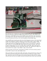
Plug the RS-232 RJ45/DB25 plug into the X1 DB25F on the control board. The control board
uses a straight cable connection. The Null modem is hardwired on the LANCNC control board.
In a later step the other end of the CAT5 cable will plug into the RJ45/DB25 plug.
The round DIN power plug will go into
J1
on the control board shown above. The control board
requires any volt between 7-30VDC to operate (6 watts or 500mA with a +12VDC supply). The
center is +VDC and the outside barrel of the plug is 0 VDC common (DC ground). Test the
voltage and polarity before plugging into the LANCNC board. Use the CNCs DC common (0
VDC) on the pin 7 on the machines DB25 RS232 plug, this is typical, but please verify in the
machines wiring manual. Note if you are unsure where to tap the DC voltage inside the CNC,
purchase the optional DIN rail power supply from Calmotion. This optional power supply uses
120 to 240VAC line voltage to created the DC voltage for the LANCNC.
Plug the customer’s Ethernet cable coming from the customer’s LAN network directly into the
silver
J7
RJ45 connector on the small daughter board.
Make sure the SD card is latched into the SD card housing. Pressing the SD card in will eject the
card. Pressing the SD card in again will latch the card.Locate the serial port connector of the
CNC. Attach one end of the CAT5 cable to the serial port connector of the LANCNC controller.
Attach the other end to one of the DB25 connectors included with the kit. Both male and female
X1
RS-232 Serial
J7
Ethernet
Port
J1
7-30VDC
SD card


