background image

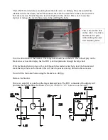
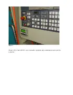
The LANCNC kit includes a mounting bezel that also acts as a drill jig. Once the installer has 
identified where the display should be mounted, the mark the small hole in the center and drill a 
hole the same size. Mount the plate, level and tighten to the cabinet. Please note to use best 
method to manage the metal chips created when drilling the holes.

Note the orientation of the bracket.  The large hole should be on the left.  Place the display on the 
bracket to see how the display has the RJ11 jack that protrudes through the large hole.

With the bracket held in place with a bolt through the smaller center hole, level the bracket and 
mark the larger hole on the bracket, this will need to punched or step drilled to this same size.

Now drill the four outer holes using the bracket as a drill jig.

Remove the bracket.

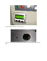
Hole saw, step drill or punch out the larger diameter hole. The RJ11 connector of the display will 
protrude through this hole. (

McMaster Carr p/n 3789A18, 1 1/8” hole saw can be used

).

This is the smaller hole 
in the center.  Use this to 
hold bracket in place 
while drilling the outer 
four mounting holes.

Содержание LANCNC

Страница 1: ...LANCNC LANCNC RMT FTP Data Server for CNC Controls Machine Mount instructions 2008 2018 Calmotion LLC All rights reserved Calmotion LLC 7536 San Fernando Road Sun Valley CA 91352 www calmotion com...

Страница 2: ...l connection to the control box for the purposes of input output of CNC data Typically the CNC manufacturer refers this as read and punch tape functions Please review the instruction manual thoroughly...

Страница 3: ...t to see how the display has the RJ11 jack that protrudes through the large hole With the bracket held in place with a bolt through the smaller center hole level the bracket and mark the larger hole o...

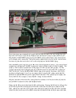
Страница 4: ...Mount the display and bracket to the control box Inside the cabinet the RJ11 and the potentiometer should be visible through the large diameter hole...

Страница 5: ...will need to be within the distance of the display cable serial cable and the power plug Secure the din rail as shown below Attach the din rail clips to the LANCNC controller and mount to the din rail...

Страница 6: ...NCNC board Use the CNCs DC common 0 VDC on the pin 7 on the machines DB25 RS232 plug this is typical but please verify in the machines wiring manual Note if you are unsure where to tap the DC voltage...

Страница 7: ...e connected to ground The power supply can be anywhere in the range of 7 30 volts DC Find a suitable power source in the cabinet and connect the flying lead connections to a power source Apply power t...

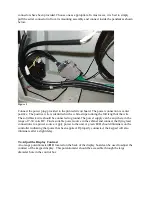
Страница 8: ...Figure 2 Please refer to the LANCNC user s manual for operation and communication set up of the LANCNC...

Отзывы: