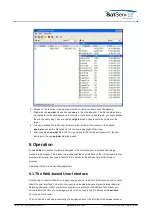
read from the position sensors.STANDBY: The STANDBY button puts the pointing loop of all
axes to 'standby' mode: Differences between measured and commanded value do not cause
the motors to be driven in this mode. Standby mode can be used for maintenance purposes
or to move the antenne by actuating the frequency inverters directly by hardware circuits. To
leave standby mode, click the STANDBY button again or RESET.
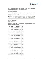
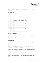
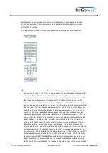
The 'Pointing' page is the main page of the ACU user interface which shows the actual antenna
pointing and some status information. The 'Pointing' page automatically refreshes once a second.
The refresh-rate may be adjusted on the setup-page from software version 2.1.007 or higher.
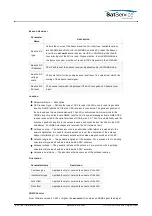
The table below describes the information shown by this page:
Parameter Name --- Description
Azimuth Elevation Polarization --- The bold printed figures show the actual antenna pointing
angles as read from the position sensors. If the polarization axis is not controlled by the ACU,
'-.---°' is displayed in the polarization field.
Xx. target value --- Below the measured angles the ACU displays the target values of the
antenna pointing. The target values are the angles which have been commanded to the
ACU. You may click to a target angle in order to change the pointing manually. The ACU
display a dialog page where you can enter the new pointing angle. If you click to the
'SUBMIT' button in this dialog page, the antenna immediately moves to the new position. To
go back to the main page without changing the pointing, click to the 'Back' button of your
Web browser.
Axis state flags --- Below the target values, for each axis there is a field reserved which
contains some state information for this axis. While the motor is running, 'MOVING' is
displayed at this place. If the motor has been stopped due to a fault or an emergency stop
request, a red label 'STOPPED' is displayed. Finally, if the ACU recognizes the activation of a
limit switch, the orange colored label 'LIMIT' is displayed in this field. If the ACU is in standby
mode, 'STANDBY' ist displayed for all axes.
Target name --- The name of the satellite the antenna is pointing to. Click to the name to get
a dialog page where you can change the name. The name is stored together with a
satellite's pointing at the
target memory
page. If you change the target pointing values, the
target name is set to 'unknown' by the ACU. Hence you first should adjust the antenna
pointing, then enter the satellite's name.
Tracking mode --- sat-nms ACUs with the tracking option installed display the actual tracking
mode / state in this field. ACUs without tracking show 'OFF' all the time. In STEP and
ADAPTIVE tracking modes this field shows what the tracking actually is doing and some
information about the tracking data in memory:
fill --- tells how many hours of step track data for calculating a model the ACU actually
has in memory. This data may be used in ADAPTIVE mode to predict the satellite
movement in case of a beacon failure. The smoothing which may be applied to the step
track also relies on this data.
age --- means the age of the most recent successful tracking step. In other words this
describes how many hours ago the beacon was lost in case of a beacon failure.
Beacon level --- This field shows the beacon level as read from the beacon receiver.
Depending on the source defined at the
Setup
page, this either is the beacon level reported
(C) 2022, SatService GmbH
www.satnms.com
ACU-19V2-UM-2209 Page 20/65

