background image


Document type: 

Title: 

Revision date: 

Revision: 

User's Manual (MUT) 

Mod. A1733-A1833-A1733B-A1833B HV Boards 

15/01/2010 


NPO: 

Filename: 

Number of pages: 

Page: 

00101/00:17XXx.MUTx/09 A1733B-A1833B_REV9.DOC 

17 


1. Introduction 

1.1 

The CAEN Universal Multichannel Power Supply System 

 
The SY 1527 system is the fully equipped, large scale experiment version of a new line 
of power supply systems which represent CAEN's latest proposal in the matter of High 
Voltage and Low Voltage Power Supplying. This system outlines a completely new 
approach to power generation and distribution by allowing to house, in the same 
mainframe, a wide range of boards with different functions, such as High/Low Voltage 
boards, generic I/O boards (temperature, pressure monitors, etc.) and branch controllers, 
where the latter are used to control other remote generators and distributors. 
 
Modularity, flexibility and reliability are the key-points of its design, enabling this module 
to meet the requirements of a wide range of experimental conditions. The latter range 
from those of LHC experiments, in which the model’s features find prior application, to 
those of other less challenging, but still demanding, High Energy Physics experiments. 
 
The mainframe is housed in a 19"-wide, 8U-high euro-mechanics rack and hosts four 
main sections: 

- the 

Board Section

, with 16 slots to house boards, distributors and branch controllers; 

- the 

Fan Tray Section

, housing 6 fans disposed on two rows; 

- the 

Power Supply Section

, which consists of the primary power supply and up to 3 

power supply units; 

- the 

CPU and Front Panel Section

 which includes all interface facilities. 

 
The User interface features the usual friendliness of the previous CAEN systems which 
now also includes a 7.7" colour LCD. A wide choice of interfaces provides full 
communication compatibility with the previous systems and the possibility of controlling 
heterogeneous external devices. 
 
Modularity has been one of the leading criteria in the design and development of the 
system: both the 

Power Supply Section

 and the 

Board Section

 are completely modular. 

The 

Power Supply Section

 allows different configurations with up to 3 power supply units 

per mainframe (up to 2250 W), while the 

Board Section

 can house up to 16 boards able 

to fulfil different functions. A new line of boards and distributors, analogous with those 
available for the SY 527 system, and a set of branch controllers has been specially 
developed for this new system. The minimum system configuration consists of the 
primary power supply, one Power Supply Unit and one board. 
The concept of modularity has been extended up to the possibility of arranging “clusters”, 
consituted by one “intelligent” SY 1527 system able to drive other “non-intelligent” 
systems, i.e. systems without CPU (to be implemented). The connections among the 
systems constituting the cluster are realised through a new CAEN interface, the Local 
Net. 
 
The extreme flexibility of the system, which allows to house indifferently, inside the same 
mainframe, boards with different functions, is further enhanced by the possibility of 
developing 

ad-hoc

 boards and even complete custom peripheral systems. The latter, 

Содержание SY 1527

Страница 1: ...Technical Information Manual MOD A 1733 A 1833 A 1733B A 1833B 12 28 CHANNEL HV BOARDS MANUAL REV 9 15 January 2010 Revision n 9 NPO 00101 00 17XXx MUTx 09...

Страница 2: ...responsibility for damages or injuries caused by an improper use of the Modules due to negligence on behalf of the User It is strongly recommended to read thoroughly the CAEN User s Manual before any...

Страница 3: ...7 2 MOD A1733 A1833 A1733B A1833B HV BOARDS 8 2 1 FUNCTIONAL DESCRIPTION 8 2 2 CHANNEL CHARACTERISTICS TABLE 9 2 3 FRONT PANEL 10 2 4 TECHNICAL SPECIFICATIONS 11 2 4 1 Packaging 11 2 4 2 External conn...

Страница 4: ...URES FIG 2 1 MOD A 1733 A 1833 LEFT AND MOD A 1733B A 1833B RIGHT FRONT PANEL 10 FIG 2 2 MOD A 1733B A 1833B HV MULTIPIN CONNECTOR 12 FIG 4 1 A MOD A1733 A 1833 SIDE VIEW B MOD A1733B A 1833B TOP VIEW...

Страница 5: ...consists of the primary power supply and up to 3 power supply units the CPU and Front Panel Section which includes all interface facilities The User interface features the usual friendliness of the pr...

Страница 6: ...r crates connected to it Live insertion and extraction of the boards which reduces the global down time and easy access to the computing core and peripherals completes the system s flexibility Easy in...

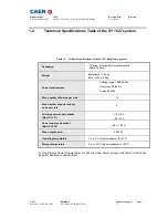
Страница 7: ...s rack Depth 720 mm Weight Mainframe 24 kg Mod A1532 3 2 kg Power requirements Voltage range 100 230 Vac Frequency 50 60 Hz Power 3400 W Max number of boards per crate 16 Max number of power supply un...

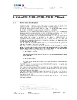
Страница 8: ...for each channel in the range 1 500 V s in 1 V s steps The output current is monitored with 20 nA 200 nA resolution depending on current range if a channel tries to draw a current larger than its pro...

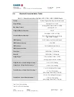
Страница 9: ...n current range Mod A 1833 A 1833B VMAX hardware 0 4 kV common for all the board channels VMAX hardware accuracy 2 of FSR VMAX software 0 4 kV settable for each channel VMAX software resolution 1 V Ra...

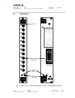
Страница 10: ...U T P U T S SCALER POSITIVE 12 CH Mod V560E Mod A 1833P HV EN input connector Channel output connector Channel LED SCALER Mod V560E Mod A1833BP 28 CH HV EN MAXV GND GND GND GND GND NC NC NC NC NC 6 N...

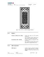
Страница 11: ...733 A 1833 Mechanical specifications HV coaxial connectors Radiall SHVR317580 type Electrical specifications high voltage output according to specifications given in Table 2 1 p 9 CH 0 27 A 1733B A 18...

Страница 12: ...r positive polarity version yellow LEDs for negative polarity version HV ON LED A 1733B A1833B Function it lights up if at least one output channel is on Type red LED for positive polarity version yel...

Страница 13: ...ct only as specified Only qualified personnel should perform service procedures Avoid Electric Overload To avoid electric shock or fire hazard do not apply a voltage to a load that is outside the rang...

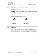
Страница 14: ...tes an injury hazard not immediately accessible as you read the marking CAUTION indicates a hazard to property including the product The following symbols may appear on the product DANGER ATTENTION Hi...

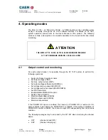
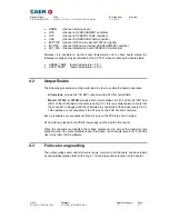
Страница 15: ...t control and monitoring For each output channel it is possible through the SY 1527 system to perform the following operations Assign to channel a symbolic name Set output voltage VSET Set max output...

Страница 16: ...ormed in order to enable the board s operation All versions provide the HV EN connector with a 50 Ohm termination Mod A 1733B A 1833B provide short circuit between Pin 51 and Pin 52 IINT and IEXT of t...

Страница 17: ...ip Switch side view T A B C 4 3 2 1 A B Dip Switch T A B C 4 3 2 1 Channels Channels Channels Channels Channels Channels Channels Fig 4 1 A Mod A1733 A 1833 side view B Mod A1733B A 1833B top view In...

Отзывы: