background image

RIVER IDROTECH 18 - 24 - 24H2O

32

8.3 

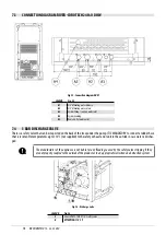
FUME CONDUIT CLEANING

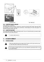
The exhaust system must be cleaned every 2/3 months.

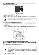
Fig. 53 - Fume conduit cleaning

•  Remove the inspection lid of the T-union (see 

Fig. 53

).

•  Extract the ash which has accumulated in the inner.

•  After cleaning repeat the operation in reverse order, checking the condition and efficiency of the gasket, and if necessary 

replace it.

It is important to sealed the cap othrwise noxiuous fumes will propagate among the room.

8.4 

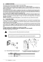
SMOKE EXTRACTOR COMPARTMENT CLEANING

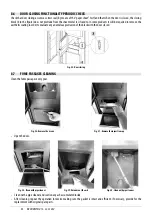
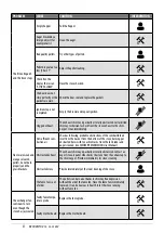
At the back of ash drawer “D”, you will find smoke cover “E”, which must be removed to clean the smoke extractor. Therefore:

•  loosen screws “s” 

•  remove smoke cover “E”

At this point, use a vacuum cleaner nozzle to remove the ash and soot that have accumulated in the lower exchanger shown by the 

arrow. Before reinstalling cover “E”, we recommend replacing gasket “F”

Before vacuuming the ash, we recommend cleaning the inner walls of the stove with a scraper.

Fig. 54 - Lower compartment cleaning

8.5 

CLEANING THE SMOKE EXTRACTION SYSTEM AND GENERAL CHECKS

Clean the smoke exhaust system especially near the “T”-fittings, elbows, and any horizontal sections of the smoke 

duct.

Contact a qualified chimney sweep to periodically clean the flue.

Check the ceramic fibre gasket seal on the stove door. If necessary, order new gaskets from the dealer for replacement or contact 

an authorised service centre to perform the entire operation.

ATTENTION:

The fume exhaust system cleaning frequency depends on stove use and its installation.

We recommend contacting an authorised service centre for the end-of-season cleaning and maintenance 

operations because the centre will perform an overall check of the parts, as well as the above-mentioned 

operations.

Содержание RIVER IDROTECH 18

Страница 1: ...INSTALLER MANUAL PELLET THERMOSTOVE EN OriginalInstructions 2022CADELsrl Allrightsreserved Tuttiidirittiriservati new RIVER IDROTECH 18 RIVER IDROTECH 24 RIVER IDROTECH 24H2 O ...

Страница 2: ...DHW 16 7 3 CONNECTION DIAGRAM RIVER IDROTECH 24 H2O DHW 17 7 4 3 BAR DISCHARGEVALVE 17 7 5 WASHINGTHE SYSTEM 18 7 6 FILLINGTHE SYSTEM 18 7 7 WATER CHARACTERISTICS 19 7 8 SYSTEM CONFIGURATION 19 7 9 CONFIGURATION 1 19 7 9 1 SYSTEM WITH DIRECT PELLET STOVE AND ROOM PROBE OR EXTERNALTHERMOSTAT OPTIONAL 19 7 10 CONFIGURATION 2 21 7 11 CONFIGURATION 3 23 7 12 CONFIGURATION 4 25 7 13 CONFIGURATION 5 26 ...

Страница 3: ...CKING TheproductispackagedinarecyclablecardboardboxaccordingtoRESYstandards onawoodpallet Allthepackagingmaterialscan bereusedforsimilarpurposesor intheevent disposedofaswasteassimilabletourbansolidwaste followingthestandardsinforce After having removed the packaging make sure the product is intact Handle the product with appropriate means respecting the safety standards in force Do not overturn t...

Страница 4: ...thatthesmokeductandpipeare coaxial If the stove needs to be connected to an exhaust pipe that goes through the back wall to go into the flue be extremely careful not to force it Forcingthestovesmokeexhaustorusingitimproperlytoliftorpositionthestovewillirreversiblycompromise itsfunction Turning the feet clockwise lowers the stove Turning the feet anticlockwise raises the stove see below Fig 4 Foota...

Страница 5: ...ved with the utmost care 3 CHIMNEY FLUE 3 1 PREPARING THE SMOKE EXPULSION SYSTEM The combustion product expulsion system is a particularly important element for the proper operation of the appliance and must be correctly sized according to EN 13384 1 Its creation adaptation verification must always be carried out by a legally qualified operator and must comply with the regula tions in force in the...

Страница 6: ...ion 6 5 mt 10 mt Maximum length with 3 unions 4 5 mt 8 mt Maximum number of unions 3 3 Level section minimum inclination 3 4 mt 4 mt Installation at a height above 1200 m a s l NO Obligatory 3 4 FLUE CHIMNEY OR PIPED DUCT When creating the flue in particular comply with the following requirements comply with the applicable product standard EN 1856 EN 1857 EN 1457 EN 1806 EN 13063 be made with suit...

Страница 7: ...ble the internal section of the chimney prevent the penetration of rain or snow ensure the outlet of smoke even in the event of wind windproof chimneypot the height of outflow must be beyond the reflux area refer to national regulations to identify the reflux area always be built at a distance from antennas or dishes and never be used as a support unless there are specific national derogations cle...

Страница 8: ...he installation room can take place with a free air inlet or by channelling the air directly to the outside The free air inlet must be be made at floor level and in any case not higher than the height of the appliance always be protected with an outer grille and in such a way that it cannot be obstructed by any object have a minimum total free area of 80 cm2 net of the grille The presence of other...

Страница 9: ...ne linear metre Intheeventthecombustionairisductedonunsealedproducts stillverifythatnomorethan4Paofnegativepressureiscreated insidetheinstallationroomwithrespecttotheoutside otherwiseprovideforanadditionalairintakeintheroom Below 15 kW Air duct diameter Maximum length smooth duct Maximum length corrugated duct 50 mm 2 m 1 m 60 mm 3 m 2 m 80 mm 7 m 4 m 100 mm 12 m 9 m Above 15 kW Air duct diameter ...

Страница 10: ...4 24H2O 10 Fig 12 Phase1 Connect the air intake pipe to the combustion air pipe of the stove and tighten everything with a clamp see Fig 12 5 EXAMPLES OF INSTALLATION DIAMETERS AND LENGTHS TO BE SIZED Fig 13 Chimneyflue ...

Страница 11: ...lic system must be installed in compliance with the laws and regulations in force and carried out by a qualified technician who must issue a declaration of conformity of the system to the system manager and shall undertake full responsibility for final installation and consequent good operation of the product The manufacturer declines all responsibility in the event of installations that do not co...

Страница 12: ...trequireahighdegreeofinsulationsuchas passive or high energy efficiency houses Thanks to this technology there is no risk of smoke emissions in the room and no air inlets hence not even the relevant ventilation grilles are required in the installation premises Consequently there will be more draughts of cold air in the room thus making it more comfortable and increasing the overall efficiency of t...

Страница 13: ...ionductsandtheir subsequent restoration For generators connected to the hydraulic system a connection must be provided between the system itself and the product so that during extraordinary maintenance carried out by a qualified technician it is possible to move the generator 1 by at least 50 cm from adjacent walls without emptying the system e g by using a double shut off gate or suitable flexibl...

Страница 14: ...rame proceed as follows Remove the top panel Fig 18 Fig 18 Removethepanel Fig 19 Attachtheframetothestoveintheslots Fig 20 1stslot Fig 21 2stslot Fig 22 Securetheframe 6 6 ASSEMBLING THE TOP CLADDING AND BOTTOM DOOR To assemble the cladding proceed as follows Place the top panel on the stove if maiolica Attach the top in the specific slots if in metal ...

Страница 15: ... electric connection occurs through a cable with plug put in an electric socket which is able to support charge and tension specific of every model as described in the technical datas table see FEATURES a pag 44 The plug must be easily accessible when the appliance is installed Please further assure you that your network is endowed with an efficient earth connection if it does not exist or if it i...

Страница 16: ...er operation To do this proceed as follows Connect a digital pressure switch with a tube to detect the negative pressure see Fig 32 Fig 33 Load the feed screw via appropriate function Start the stove and set Set flame to power 1 the start up time of this stove lasts between 8 and 10 minutes to ensure mini mum draught Compare the read values with those on the table Change power every 10 minutes and...

Страница 17: ...LYRECOMMENDWASHINGTHEENTIRESYSTEMBEFORECONNECTINGTHESTOVEINORDERTORE MOVERESIDUEANDBUILD UPS Always install gate valves upstream of the stove to isolate it from the hydraulic system should it be necessary to move it for routine and or special maintenance Connect the stove using flexible hoses so as not to excessi velybindthestovetothesystemandtoallowittobemovedslightly The pressure discharge valve...

Страница 18: ...that can be inspected on the back of the stove under the pump IT IS MANDATORY to connect a rubber hose thatisresistanttotemperaturesupto110 C notsupplied tothesafetyexhaustandrunittotheoutsideincasewaterisdischar ged The manufacturer of the appliance is not liable for any flooding caused by the safety valves tripping if they arenotproperlycoupledtotheoutsideoftheproductortoanappropriatecollectiona...

Страница 19: ...ing efficiency of the boiler and reduce the noise it generates FERNOX F4 is intended to be used with all heating appliances to seal micro fractures that cause small and inaccessible leaks 7 6 FILLING THE SYSTEM To fill the system the stove may be equipped with a terminal optional with a non return valve D to manually fill the heating system ifthereisnoterminal usethefillingvalveonthemainboiler Dur...

Страница 20: ...r by enabling an external room thermostat instantaneous DHW production with INTEGRATED plate exchanger 2 2 Room temperature management via probe on the stove or by enabling an external room thermostat DHW production for boiler or storage tank with EXTERNAL thermostat CONNECTEDTOTHE ELECTRONIC BOARD optional DISCONNECT ANY 3 WAYVALVES AND INTERNAL FLOW SWITCHES 3 Room temperature management via pro...

Страница 21: ...ATION 1 Hydraulic diagram Fig 39 Configuration1 LEGEND Fig 39 1 Anti condensationvalve 2 Externalthermostat 3 Roomprobe 4 Electronicboard 5 Stove 6 Zonevalve 7 Expansionvessel A Wiring diagram for connecting external thermostat and zone valve in the case of several val ves connectinparallel B Wiringdiagramforconnectingtheexternalthermostat ...

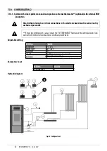
Страница 22: ...orised personnel If the external thermostat is used activate the EXT THERMOSTAT function on the control panel and con nectitdirectlytotheelectronicboard seeelectricalsystembelow Adjustable setting SETTING VALUES ROOMTEMP 5 C 35 C WATERTEMP 30 C 80 C DHWTEMP 75 C SEASON WINTER summer may be activated AUTO ECO OFF with winter setting ON with summer setting cannot be deactivated Parameters to set SET...

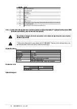
Страница 23: ...ith external DHW production controlled by external thermostat optional All activities relating to electrical connections in the electronic board must be carried out by authorised personnel If the external thermostat is used activate the EXT THERMOSTAT function on the control panel and con nectitdirectlytotheelectronicboard seeelectricalsystembelow Adjustable setting SETTING VALUES ROOMTEMP 5 C 35 ...

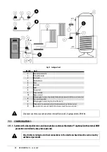
Страница 24: ...amforconnectingtheexternalthermostat C Thermostattobeconnecteddirectlytotheelectronicboard seeelectricalsystem D 3 wayvalvetobeconnecteddirectlytotheelectronicboard seeelectricalsystem Disconnectanythree wayvalveandstoveinternalflowswitch ifequippedwithaDHWkit 7 11 CONFIGURATION 3 7 11 1 System with direct pellet stove and room probe or external thermostat optional with external DHW production con...

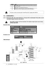
Страница 25: ...ES ROOMTEMP 5 C 35 C WATERTEMP 30 C 80 C DHWTEMP 75 C SEASON WINTER summer may be activated AUTO ECO OFF with winter setting ON with summer setting cannot be deactivated Adjustable setting SETTING VALUES CONFIGURATION 3 Hydraulic diagram Fig 42 Configuration3 LEGEND Fig 42 1 Anti condensationvalve 2 Externalthermostat 3 Roomprobe 4 Electronicboard 5 Stove 6 Zonevalve 7 DHW 8 Storagetank 9 BoxNTCpr...

Страница 26: ...12 1 System with pellet stove connected directly to a storage tank for maintaining the temperature set and controlled through a thermostat connected to it All activities relating to electrical connections in the electronic board must be carried out by authorised personnel Adjustable setting SETTING VALUES ROOMTEMP Cannot be activated EXTERNALTHERMOSTAT ON connect storage tank thermostat SEASON WIN...

Страница 27: ...7 13 CONFIGURATION 5 7 13 1 System with pellet stove connected directly to a storage tank for maintaining the temperature set and controlled through a thermostat connected to it All activities relating to electrical connections in the electronic board must be carried out by authorised personnel Adjustable setting SETTING VALUES ROOMTEMP Cannot be activated EXTERNALTHERMOSTAT ON connect storage tan...

Страница 28: ...y B NTCprobetobeconnecteddirectlytotheelectronicboard seeelectricalsystem Disconnectanythree wayvalveandstoveinternalflowswitch ifequippedwithaDHWkit 7 14 CONFIGURATION WITH STORAGE TANK AND AUXILIARY WALL MOUNTED BOILER EXAMPLE 7 14 1 System with pellet stove connected to a storage tank with auxiliary wall mounted boiler All activities relating to electrical connections in the electronic board mu...

Страница 29: ...alve 10 Expansionvessel 11 HotH2Omanifold 12 ColdH2Omanifold 13 Radiator 14 Auxiliaryboiler 15 Zonevalve A Boilerpowersupply B Auxiliarysystempumpsupply C Alarmsignal 7 15 OPERATING MODE The operating mode for hydro boilers is AUTOMATIC only manual mode is not envisioned Flame modulation is managed accor ding to the System configuration of the room probe placed on the rear of the appliance see dra...

Страница 30: ...g The connections to the terminal board must be made with cables with a maximum length of 3 metres regardless of whether they are signal or power cables Fig 47 Unscrewside Fig 48 Removeside Fig 49 Connections REAR PANEL If maintenance must be performed on a component of the stove the rear panel can be removed if the distances from the walls allow it otherwise the maintenance can be performed by re...

Страница 31: ... a year It is also necessary to have the combustion chamber motors and fans cleaned and to have the gaskets and the electronical elements checked at least once a year AlltheseoperationsmustbeplannedintimewithyourAutorizedTechnicalAssistanceService After a long ineffective time before turning on the stove check if there are obstructions in the fume exhaust If the stove had been using continuously a...

Страница 32: ...gershownbythe arrow Before reinstalling cover E we recommend replacing gasket F Before vacuuming the ash we recommend cleaning the inner walls of the stove with a scraper Fig 54 Lowercompartmentcleaning 8 5 CLEANING THE SMOKE EXTRACTION SYSTEM AND GENERAL CHECKS Clean the smoke exhaust system especially near the T fittings elbows and any horizontal sections of the smoke duct Contact a qualified ch...

Страница 33: ...oating in order to evaluate any anomalous protrusion of the block with the door closed Fig 55 Doorclosing 8 7 FUME PASSAGES CLEANING Clean the fume passages every year Fig 56 Removethescrews Fig 57 Removetheinspectioncap Open the door Fig 58 Cleanwithpipecleaner Fig 59 Vacuumouttheash Fig 60 Cleanwithpipecleaner Clean with a pipe cleaner and suction any ash accumulated inside After cleaning repeat...

Страница 34: ...come worn and or damaged thereby requiring replacement once a year to ensure proper system operation Replace by following the instructions below Remove the top Remove the first ceramic or steel side panel depending on the type of stove Unscrew the screw washer rubber spacer roller shown in fig A C on both sides of the cover Then assemble the new kit Align the screw washer rubber spacer roller as s...

Страница 35: ...ce This operation must be executed at least once a year 8 11 GASKET REPLACEMENT Incaseofdeteriorationoffiredoor hopperorfumechambergaskets itisnecessary toreplacethembyanautorizedtechnicianin order to guarantee the good running of the stove Useexclusivelyoriginalspareparts 9 IN CASE OF ANOMALY 9 1 PROBLEM SOLVING Before of every Authorized Technician intervention the same Technician has the duty t...

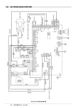
Страница 36: ...aulty flat cable Replace the flat cable Faulty electronic board Replace the mother board Pellets do not reach the combustion chamber Empty hopper Full the hopper Open fire door or open pellet door Close fire door and pellet door and check that there are no pellet grains at the gasket level Clogged stove Fume chamber cleaning Auger blocked by a foreign object for example nails Clean the auger The a...

Страница 37: ...properly and the glass blackens Not sufficient com bustion air Check as following probable obstructions of the combustible air inlet from the back or from the bottom of the stove burning pot obstructed holes with too ash remains Have the fan blades and auger cleaned see SMOKE RPMVARIATION User Manual Obstructed exhaust The exhaust chimney is partially or totally obsturcted Contact an expert stove ...

Страница 38: ... Ambient temperatu re reached The stove is at its minimum value Increase the desired ambient temperature Stove running and display showing Smoke Overtepe rature Reached fume outlet limit temperature The stove runs at minimum NO PROBLEM The stove s smoke duct produces condensation Low smoke tempe rature Check that the flue is not clogged Increase stove power to minimum pellet drop and fan revs Inst...

Страница 39: ...ircuit board Replace board The boiler does not start Power failure Make sure the power cable is plugged in and the main switch is in the I position Blown fuse Replace the fuse Clogged smoke duct or exhaust Clean the smoke exhaust and or smoke duct Water temperature probe has tripped Call customer service Temperature does not increase with the boiler working Improper combu stion adjustment Check re...

Страница 40: ...t to a higher temperature Replace it if necessary if remote The circulator does not turn because it is blocked Release the circulator by removing the cap and turning the shaft with a screwdriver The circulator does not turn Check its electrical connections replace it if necessary Air inside the radiators Bleed the radiators No HEATING water comes out Circulator pump blocked Release the circulator ...

Страница 41: ...RIVERIDROTECH18 24 24H2O 41 10 TECHNICAL DATAS 10 1 ELECTRONIC BOARD WITHOUT DHW Fig 67 ElectricalboardwithoutDHW ...

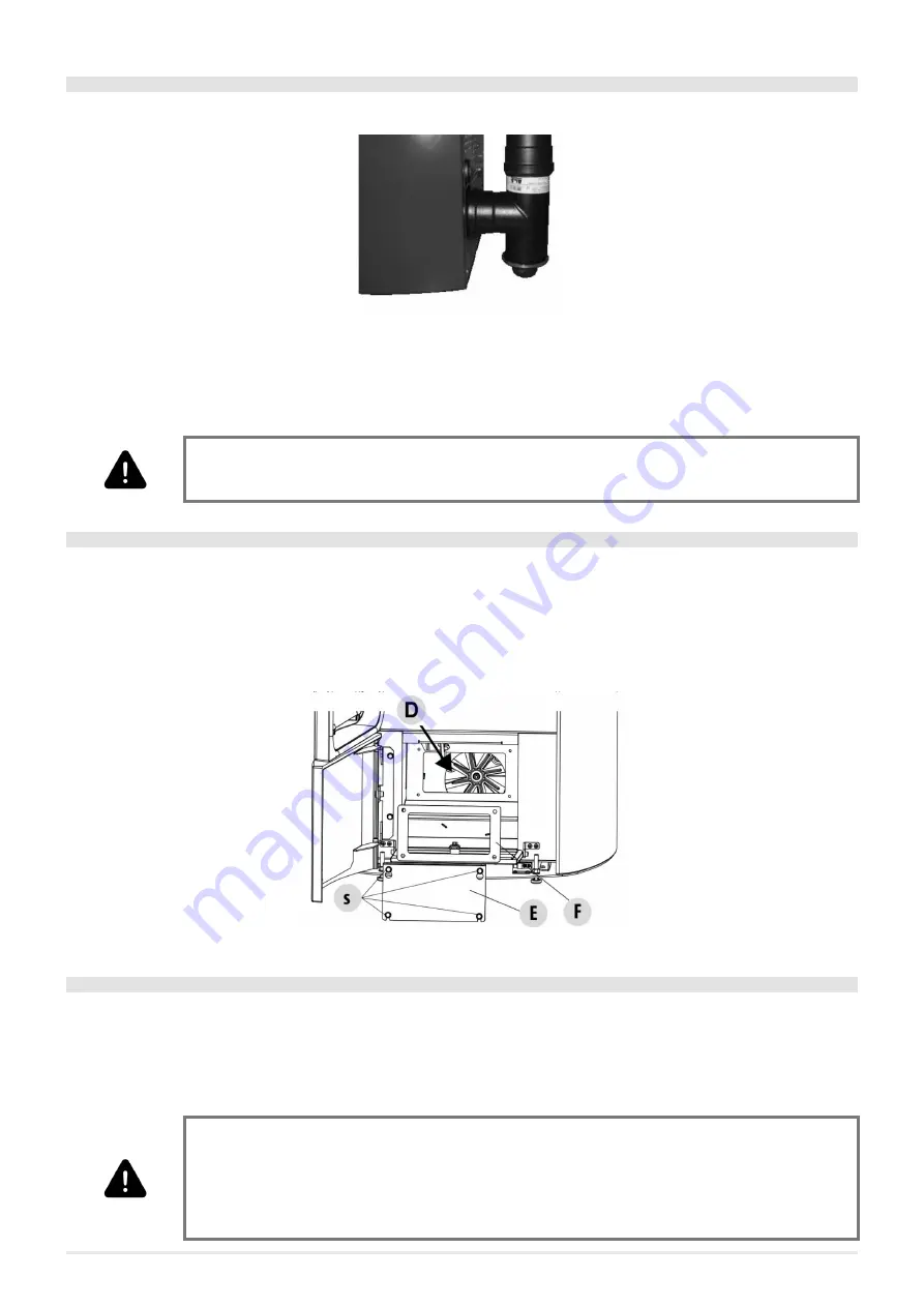
Страница 42: ...RIVERIDROTECH18 24 24H2O 42 10 2 ELECTRONIC BOARD WITH DHW Fig 68 ElectricalboardwithDHW ...

Страница 43: ...onalboilerreturn 16 Neutral 17 18 19 20 SMOKEPROBE 21 EXTERNALROOMTHERMOSTATORFORBOILER 22 STOVEINTERNALROOMPROBE 23 Cleanermicroswitch 24 ExternalPuffer_boilerprobe 25 26 BoilerH20temperatureprobe 26 27 Fluegasfanencoder 28 Flowswitch Seenote 29 Wi Ficonnection 30 Interfaceconnection service 31 Controlpanel 32 Recirculationpumpphase 33 3 wayvalveDHWphase 34 3 wayvalveheatingphase 35 Cleanerpowers...

Страница 44: ...ws Remove the frame see the dedicated chapters After these operations you can have access at the following components geared motor ignition plug ambient fan fume fan ambient probe fume probe thermostat electronic board pressostat For cleaning or replacemente of the auger it is necessary to unscrew the three bolt of the geared motor and to extract it un screw the two screws lying under the geared m...

Страница 45: ...2 mg Nm3 CHIMNEY DEPRESSION Max 12 Pa 2 Pa 12 Pa 2 Pa 12 Pa 2 Pa ON SHARED CHIMNEY FLUE NO NO NO FUME OUTLET DIAMETER Ø80 mm Ø80 mm Ø80 mm COMBUSTIBLE Pellet Ø6 7 mm Pellet Ø6 7 mm Pellet Ø6 7 mm PELLETS HEATINGVALUE 5 kWh kg 5 kWh kg 5 kWh kg PELLETS HUMIDITY 10 10 10 HEATINGVOLUME 18 20 C Coeff 0 045 kW Min Max 123 496 m3 123 678 m3 123 678 m3 HOURLY CONSUMPTION Min Max 1 3 9 kg h 1 5 4 kg h 1 5...

Страница 46: ...NOTE ...

Страница 47: ...NOTE ...

Страница 48: ...CADEL srl 31025 S Lucia di Piave TV Via Foresto sud 7 Italy Tel 39 0438 738669 Fax 39 0438 73343 www cadelsrl com www free point it www pegasoheating com Rev 00 2022 ...

Отзывы: