


TESTING AND TROUBLESHOOTING
Page 4-2
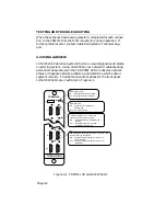
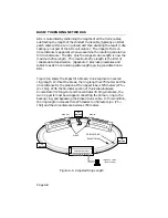
SN
16Mb
ERR
TRMIM-10R
1
7
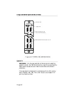
LINK ATTACHED (10 - Green) LED
(one for each trunk coupling port)
ON - Respective station is inserted into
the ring.
OFF - Respective station is removed
(bypassed) from the ring.
ERR (Red) LED
ON - Hardware error detected in
TRMIM-10R
OFF - Normal operation
16Mb (Yellow) LED
ON - Ring speed set for 16 Mbit/sec
OFF - Ring speed set for 4 Mbit/sec
TOKEN RING
5
6
RI
RO
RING-IN/RING-OUT PORT STATUS (2 - Green) LED
(one for each ring connection)
ON - Respective Ring-In/Ring-Out port is in a
non-wrap state
OFF - Respective Ring-In/Ring-Out port is in a
wrap state
When these checks have been successfully completed for each connec-
tion to the TRMIM-10R, the MIM is ready for normal operation. If
further problems occur, contact Cabletron Systems' Technical Sup-
port.
4.2 USING LANVIEW
LANVIEW is Cabletron Systems' built-in visual diagnostic and status
monitoring system. Using LANVIEW, your network troubleshooting
personnel can quickly scan the LANVIEW LEDs to observe network
status or diagnose network problems, and determine which node or
segment is faulty. The definitions and locations for the front panel
LANVIEW LEDs are illustrated in Figure 4-1.
Figure 4-1. TRMIM-10R LANVIEW LEDs


