


REQUIREMENTS/SPECIFICATIONS
Page 2-3
•
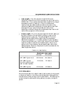
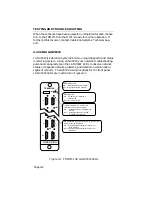
Lobe Length - This is the physical length of STP cable
connecting a station to the trunk coupling unit (TCU) port on the
TRMIM-10R. The recommended maximum length for the longest
lobe cable is shown in Table 2-2. This is a recommended
maximum because cable length calculations for passive ring
connections described in Appendix C could produce a maximum
lobe length for your network that differs from this limit.
Installing a lobe that exceeds the recommended maximum could
restrict future expansion of the network.
•
Trunk Length - This is the physical length of the STP cabling in
the main ring path, from Ring-Out to Ring-In on each of the
attached token ring devices. The cable budget for the trunk
cabling must be determined by performing the calculations
described in Appendix C. In a totally passive ring (no repeaters
or active concentrators, etc. on the ring), the entire trunk length
must be included in calculation of cable lengths. When only a
portion of the ring is passive, the combined length of the trunk
cabling between the active components must be considered in the
cable length calculations.
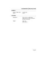
Table 2-2. Lobe Cabling
Maximum Lobe Length
4 Mbit/sec
16 Mbit/sec
STP (IBM Types 1 & 2)
200 meters
100 meters
STP (IBM Type 6)
30 meters
30 meters
(only for station to wall
jack and patch panels)
STP (IBM Type 9)
130 meters
65 meters
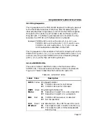
2.1.3 Attenuation
Maximum attenuation for specific cable types according to ring speed,
is shown by Table 2-3. Since there are two possible ring speeds, two
frequencies are listed, namely 4.0 MHz and 16 MHz. The attenuation
values include the attenuation of the cables, connectors, and patch
panels.


