DCE cables have female connectors at the user end, and DTE
cables have male connectors.
Configure the Video Device
Follow the appropriate procedure to configure the FRX6000 to operate with an
attached Auxiliary Console (ASCII terminal) or VGA monitor.
A VGA monitor may be necessary even if you are configuring the
node to operate with an ASCII terminal. See step 1 under
"Auxiliary Console."
Auxiliary Console
This feature allows an FRX6000 to be controlled from an asynchronous
(ASCII) terminal connected—directly or via modems—to the node's COM1
serial port.
The following items are shipped with each FRX6000, to allow for different
methods of connecting an auxiliary console:
●
Cable, DB9S to DB9S, for connecting the node's COM1 port directly to
a PC with software emulating an ASCII terminal.
●
Adapter, DB9P to DB25S, for connecting the node directly (via the
above cable) to an ASCII terminal.
●
Cable, DB9S to DB25P, for connecting an ASCII terminal via modem
to the COM1 port.
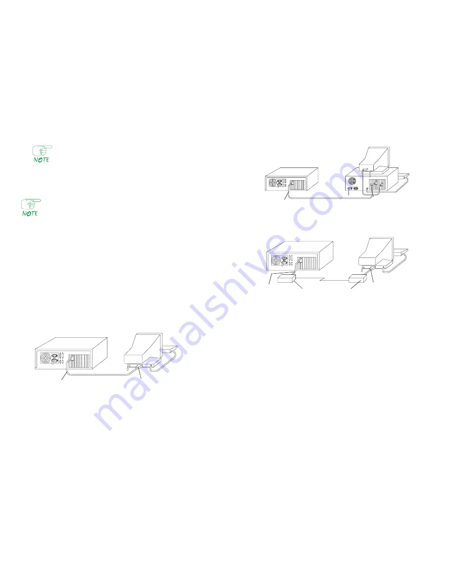
Figure 4 through Figure 6 show the cabling configurations.
Figure 4
Auxiliary Console Cabling Example 1
Installation & Setup Guide
5
Figure 5
Auxiliary Console Cabling Example 2
Figure 6
Auxiliary Console Cabling Example 3
Follow this procedure to set up the auxiliary console:
1. If the terminal's speed is 9600 bps, go to step 11. If the speed is 1200,
2400, or 4800 bps, you must reconfigure the FRX6000 software, which
requires a VGA monitor (and keyboard). Connect the monitor to the VGA
port on the FRX6000 (see Figure 1) and plug the keyboard cable into the
keyboard connector.
2. Plug the FRX6000 and VGA monitor power cables into the appropriate
power source, then switch the monitor on.
3. Insert the FRX6000 System Disk into the node's drive A and switch the
node on.
4. A message concerning LAN card configuration will be displayed. When
prompted:
Strike any key when ready
, press
[Enter]
.
5. When asked:
Will you be using an Async terminal to configure your
FRX6000?
, press
[Y]
.
6
FRX6000
FRX6000
ASCII Terminal
Cabletron Cable FRX-PC-CAB,
DB9S to DB9S
Cabletron Adapter FRX-9/25-ADAP,
DB9P to DB25S
FRX6000
PC
Cabletron Cable FRX-PC-CAB, DB9S to DB9S
FRX6000
ASCII Terminal
Auto-answer Modems
Cabletron Cable,
FRX-MOD-CAB,
DB9S to DB25P
RS-232 Cable


