


B
ASICS
Once your cabling is complete, power on the CyberSWITCH simply by plugging its power cord
into an electrical outlet. During the powering on sequence, the CyberSWITCH’s LED indicators
provide valuable information. We provide you with instructions for “reading” the LED indicators.
After powering on, but before putting the CyberSWITCH into normal operation, we recommend
that you read the Release Notes for important information.
R
EADING
THE
LED I
NDICATORS
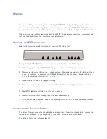
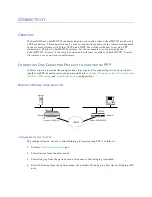
Refer to the following graphic for locating specific LED indicators:
During the CyberSWITCH’s power on sequence, you should see the following:
1.
After plugging the CyberSWITCH in, the power indicator will light up and stay lit.
2.
The service indicator will light up for the duration of the initialization tests. It will then blink if
there is a problem. For example, it will blink if your LAN is not properly terminated. For
further information, refer to
Trouble Shooting
.
3.
The RX indicator blinks during port testing.
4.
If you are using a 10BaseT connection, the 10BaseT indicator will light up if the connection is
good.
5.
The SYNC indicator will light up if layer 1 comes up.
6.
The D-CHAN indicator will light up if the data link comes up.
7.
After power on is complete, check the log messages (issue the
dr
console command) for any
warning or error messages.
A
CCESSING
THE
R
ELEASE
N
OTES
The Release Notes provide release highlights and important information related to this release that
should be reviewed before you begin the system’s installation and configuration.
The Release Notes are located on the CD


