background image

4

4

Introduction

1.1 

Instructions

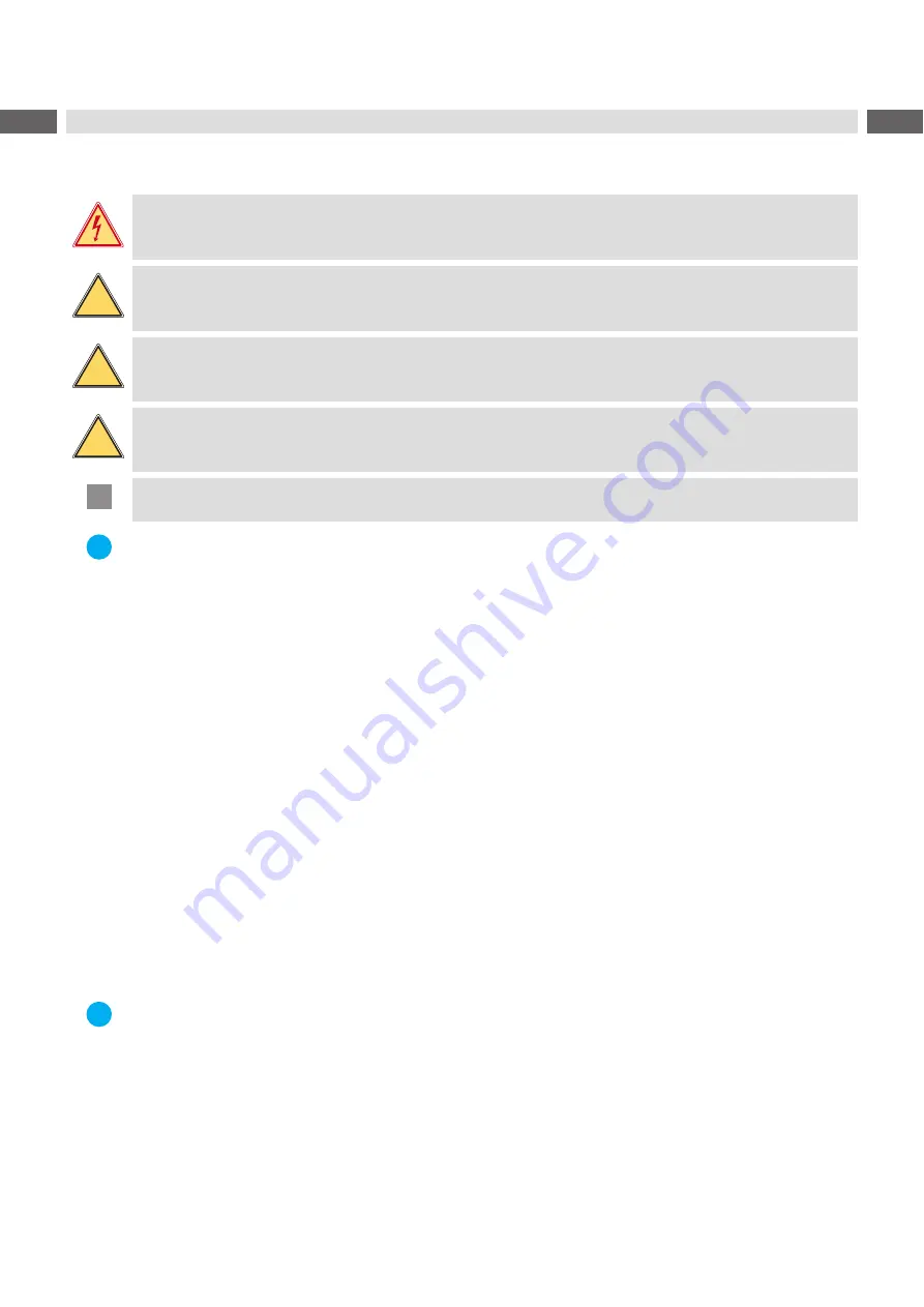
Important information and instructions in this documentation are indicated as follows:

Danger!

Draws attention to an exceptionally great, imminent danger to health or life due to dangerous electrical 
voltage.

!

Danger!

Draws attention to a danger with high risk that, if not avoided, will result in death or serious injury.

!

Warning!

Draws attention to a danger with medium risk that, if not avoided, may result in death or serious injury.

!

Caution!

Draws attention to a danger with low risk that, if not avoided, may result in minor or moderate injury.

!

Attention!

Draws attention to potential risk of property damage or loss of quality.

i

Note!

Advice on facilitating the work-flow, or information on important steps.



Environment! 

Tips for environmental protection.

Handling instructions.

Reference to chapter, position, image number or document.

Option (accessories, peripherals, special equipment).

Time

Viewed in the display/monitor.

1.2 

Intended Use

• 

The printer is designed for the integration into a production line. It is intended exclusively for printing suitable 
materials that have been approved by the manufacturer and for coupling a cab or non-cab applicator which 
transfers labels from the printer to a product. Any other use or use going beyond this shall be regarded as 
improper use. The manufacturer/supplier shall not be liable for damage resulting from unauthorized use; the user 
shall bear the risk alone.

• 

The device is manufactured in accordance with the current technological status and the recognized safety rules. 
However, danger to the life and limb of the user or third parties and/or damage to the device and other tangible 
assets can arise during use. 

• 

The device may only be used for its intended purpose and if it is in perfect working order, and it must be used with 
regard to safety and dangers as stated in the operating manual. 

• 

Usage for the intended purpose also includes complying with the manual.

i

Note! 
The complete documentation is included in the scope of delivery on DVD, and can also currently be found in 
the Internet.

Содержание HERMES Q Series

Страница 1: ...Assembly Instructions HERMES Q MADE IN GERMANY Label Printer ...

Страница 2: ...rding questions or suggestions please contact cab Produkttechnik GmbH Co KG Germany Topicality Due to the constant further development of our products discrepancies between documentation and product may occur For the current edition please see www cab de Terms and conditions Deliveries and services are carried out according to the general sales conditions of cab Assembly Instructions for the follo...

Страница 3: ...4 Guiding the Liner to the Internal Rewinder 17 4 2 Setting the Head Locking System 18 4 3 Setting the Peel off Edge 18 4 4 Loading Transfer Ribbon 19 4 5 Setting the Feed Path of the Transfer Ribbon 20 5 Printing Operation 21 5 1 Printhead Protection 21 5 2 Synchronization of the Paper Feed 21 5 3 Peel off Mode 21 5 4 Ribbon Saving 21 6 Cleaning 22 6 1 Cleaning Information 22 6 2 Cleaning the Pri...

Страница 4: ...isplay monitor 1 2 Intended Use The printer is designed for the integration into a production line It is intended exclusively for printing suitable materials that have been approved by the manufacturer and for coupling a cab or non cab applicator which transfers labels from the printer to a product Any other use or use going beyond this shall be regarded as improper use The manufacturer supplier s...

Страница 5: ...er at the outside only Do not reach into the swivel range of the cover Perform only those actions described in this operating manual Work going beyond this may only be performed by trained personnel or service technicians Unauthorized interference with electronic modules or their software can cause malfunctions Other unauthorized work on or modifications to the device can also endanger operational...

Страница 6: ... into contact with the exposed rotating parts 1 5 Environment Obsolete devices contain valuable recyclable materials that should be sent for recycling X X Send to suitable collection points separately from residual waste The modular construction of the printer enables it to be easily disassembled into its component parts X X Send the parts for recycling The electronic circuit board of the device i...

Страница 7: ...ll retainer 9 Pivot arm with guide roller 10 Internal rewinder 11 Guide roller 12 Transport system Figure 2 Overview HERMES Q 2 3 2 2 4 5 6 7 8 9 10 11 12 2 Hinges for cab applicators 3 Control panel 4 Interface for cab applicators 5 Ribbon take up hub 6 Ribbon supply hub 7 Print mechanism 8 Roll retainer 9 Pivot arm with guide roller 10 Internal rewinder 11 Guide roller 12 Transport system Figure...

Страница 8: ...inthead retainer 15 Printhead 16 Peel off edge 17 Print roller 18 Label sensor 19 Allen key 20 Printhead locking lever Figure 4 Print mechanism 21 22 23 21 Touchscreen display 22 LED Power ON 23 USB host interface for USB memory stick or service key Figure 5 Control panel ...

Страница 9: ...connection jack 26 Slot for SD card 27 2 USB host interfaces for service key USB memory stick keyboard barcode scanner Bluetooth adapter WiFi adapter external control panel or warning light 28 USB Hi speed device interface 29 Ethernet 10 100 Base T 30 Serial RS 232 C interface 31 I O interface Figure 6 Connections ...

Страница 10: ...keep the original packaging in case the printer must be returned Attention The device and printing materials will be damaged by moisture and wetness X X Set up printers only in dry locations protected from splash water Fixing at four M6x10 drillings on the bottom side of the chassis X X Orientation upright standing only Fixing via bracket at each two M6 drillings on both sides of the chassis X X O...

Страница 11: ...socket 2 3 2 Connecting to a Computer or Computer Network Attention Inadequate or no grounding can cause malfunctions during operations Ensure that all computers and cables connected to the printer are grounded X X Connect the printer to a computer or network by a suitable cable For details of the configuration of the other interfaces Configuration Manual 2 4 Switching on the Device When all conne...

Страница 12: ...ands Programming Manual for details Settings made on the touchscreen display make the basic settings of the label printer i Note It is advantageous whenever possible to make adaptations to various print jobs in the software 3 1 Start Screen After switching on During printing In pause state After print job Figure 7 Start screen The touchscreen display is operated directly by touch To open a menu or...

Страница 13: ...ion manual All received data are stored in a lbl file Warning ribbon end Configuration manual The remaining diameter of the ribbon supply roll undershoots the set value SD card installed USB memory installed gray Bluetooth adapter installed white Bluetooth connection active WiFi connection active The WiFi strength is displayed by the number of white arcs Ethernet connection active USB connection a...

Страница 14: ... level is reached X X Start a function The will carry out the function possibly after a preparing dialogue or Select a parameter to set The setup possibilities are depending from the parameter type Logical parameters Selection parameters Numerical parameters Date time Figure 10 Samples for parameter setting Scroll bar for rough value setting Decreasing the value step by step Increasing the value s...

Страница 15: ...oading label roll 1 Turn knob 5 clockwise to release the roll retainer 4 2 Remove the margin stop 6 from the roll retainer 3 Load label roll 2 on the roll retainer 4 in such a way that the labels are visible from above after unrolling 4 Slide the roll against the wall plate 1 5 Guide the latches 7 of the margin stop 6 into the grooves 3 of the roll retainer 4 and push the margin stop against the l...

Страница 16: ... the label strip over the peel off edge 1 that the strip reaches back internal rewinder Remove the labels from the overhanging strip 4 1 3 Setting the Label Sensor 1 3 2 4 Figure 14 Setting the Label Sensor The label sensor can be shifted perpendicular to the direction of paper flow for adaptation to the label medium When the printer is switched on a yellow LED illuminates the sensor position 2 X ...

Страница 17: ...n the knob 4 clockwise until it stops 3 Guide the liner coming from the peel off edge around the transport roller 5 and the locking system 6 to the internal rewinder 1 4 Push the liner under a bracket 2 of the rewinder 1 and turn the knob 4 counterclockwise until it stops The rewinder is fully spread thus gripping the liner firmly 5 Turn the rewinder 1 counterclockwise to tighten the liner 6 Turn ...

Страница 18: ...lunger 2 with the Allen key 3 Align the outer plunger 2 to the outer label edge and tighten the threaded pin 1 4 3 Setting the Peel off Edge When operating the printer with applicator the label must be peeled off completely from the liner for the taking over by the applicator The peel off edge can be turned to optimize especially the separation of the rear label edge from the liner When the printe...

Страница 19: ...ces away from the printhead after loading 4 Hold ribbon supply hub 4 firmly and turn knob 5 counterclockwise until the transfer ribbon roll is secured 5 Slide suitable ribbon core 1 onto the transfer ribbon take up hub 2 and secure it in the same way 6 Guide transfer ribbon through the print unit as shown in Figure 19 7 Secure starting end of transfer ribbon to the transfer ribbon core 1 with adhe...

Страница 20: ...ling X X Check first the setting of the head locking system 4 2 on page 18 2 1 3 Figure 20 Setting the feed path of the transfer ribbon i Note The adjustment is best carried out during printing 1 Read current setting on the scale 1 and record if necessary 2 Turn screw 2 with Allen key and observe the behavior of the ribbon In the direction the inner edge of the transfer ribbon is tightened and the...

Страница 21: ...l not be lost by switching off the printer as long as the printhead and the transport system are kept close 5 3 Peel off Mode In Peel off mode the labels are automatically peeled off the liner after printing and presented for removal Attention X X Activate the peel off mode in the software This is done with the P command in the direct programming Programming Manual i Note The print of a label must...

Страница 22: ... impair the media transport and the print quality X X Lift the printhead X X Remove labels and transfer ribbon from the printer X X Remove deposits with roller cleaner and a soft cloth X X If the roller appears damaged replace it Service Manual 6 3 Cleaning the Printhead Cleaning intervals direct thermal printing every media roll change thermal transfer printing every ribbon roll change Substances...

Страница 23: ...he size of the barcode or move it Buffer overflow The input buffer memory is full and the computer is still transmitting data Use data transmission via protocol preferably RTS CTS Device not conn Programming addresses a non existent device Either connect this device or correct the programming File not found Requested file is not on the card Check the contents of the card Font not found Error with ...

Страница 24: ...memory card Check data of the card Backup data reformat card Remove ribbon Transfer ribbon is loaded although the printer is set to direct thermal printing for direct thermal printing remove ribbon for thermal transfer printing set the printer in the configuration or in the software to transfer printing Ribbon ink side Identified ribbon unwinding direction does not match to the setup setting Ribbo...

Страница 25: ...SCII dump mode Cancel the ASCII dump mode Printer transports label media but transfer ribbon does not move Transfer ribbon incorrectly inserted Check and if necessary correct the transfer ribbon web and the orientation of the label side Unsuitable combination of labels and transfer ribbon Use different type of ribbon Printer only prints each second label Setting of the size in the software is too ...

Страница 26: ...eight 3 200 4 320 6 320 A Label distance 2 C Width of liner 24 62 24 118 46 178 Dl Left margin 0 Dr Right margin 0 E Label thickness 0 03 0 60 F Liner thickness 0 03 0 16 G Thickness label with liner 0 06 0 76 V Label feed 5 6 8 Small label sizes thin materials or strong glue can lead to limitations Critical applications need to be tested and cleared Table 8 Label dimensions ...

Страница 27: ...00 dpi 1 0 1 0 1 0 1 0 1 0 1 0 1 0 1 0 1 0 1 0 1 0 1 0 1 0 1 0 1 0 1 0 with ribbon saver 203 dpi 300 dpi 600 dpi 1 0 1 0 1 0 1 0 2 2 0 0 1 6 0 7 0 2 2 9 0 2 2 9 K Print width 203 dpi 300 dpi 600 dpi 56 9 54 1 105 7 105 7 104 0 108 4 168 0 162 6 SX Distance gap reflective sensor material edge i e permissible distance of reflex or cut out marks to the material edge 2 26 2 60 SY Distance gap reflecti...

Страница 28: ...ce mark material edge 2 26 2 60 Z Distance virtual label front edge actual label front edge X X Adjust software settings 0 up to A recomm 0 Reflex marks must be on the back side of the material liner Label sensor for reflex marks on the top side on request Specification is valid for black marks Recognition of colored marks may fail u Preliminary tests are needed Table 10 Reflex mark dimensions 8 L...

Страница 29: ...of cut out mark 2 10 X Distance mark material edge 2 26 2 60 Y Sensor recognized virtual label front edge with gap sensor recognition Rear edge cut out Z Distance recognized front edge actual label front edge X X Adjust software settings 0 up to A P Table 11 Cut out mark dimensions Marginal cut out Long hole cut out Rectangular cut out Circular cut out Not recommended Cut out between the labels No...

Страница 30: ...30 30 9 Assembly Dimensions Figure 27 Assembly dimensions HERMES Q 2 Figure 28 Assembly dimensions HERMES Q 3 ...

Страница 31: ...N ISO 12100 2010 EN ISO 13857 2008 EN 349 1993 A1 2008 EN ISO 13849 1 2015 EN 62368 1 2014 AC 2015 Other Relevant Directives Directive 2014 30 EU relating to electromagnetic compatibility Directive 2011 65 EU on the restriction of the use of certain hazardous substances in electrical and electronic equipment Person authorised to compile the technical file Erwin Fascher Am Unterwege 18 20 99610 Söm...

Страница 32: ...EN 50581 2012 Commission delegated directive EU 2015 863 amending Annex II to Directive 2011 65 EU of the European Parliament and of the Council as regards the list of restricted substances Signed for and on behalf of the Manufacturer cab Produkttechnik Sömmerda Gesellschaft für Computer und Automationsbausteine mbH 99610 Sömmerda Sömmerda 22 10 2019 Erwin Fascher Managing Director 10 3 FCC NOTE T...

Страница 33: ...Head locking system setting 18 I Important information 4 Intended use 4 L Label sensor setting 16 License 2 Lithium battery 6 Loading labels 15 Loading transfer ribbon 19 P Peel off mode 21 Power supply 5 Printhead cleaning 22 damage 21 Print roller cleaning 22 Problem solution 25 R Reflex marks 28 Ribbon saving 21 S Safety instructions 5 Safety marking 6 Service work 5 Setting up 10 Supply voltag...

Отзывы: