36
A 8
6
Justagen, Einstellungen
Abgleiche
6.1
Justage des Druckkopfes
Zur Erzielung eines optimalen Druckbildes ist die Heizzeile
des Druckkopfes exakt zur Druckwalze auszurichten. Diese
Justage wird bei der Inbetriebnahme werksseitig vorgenom-
men. Trotzdem kann sich bei Fehlern im Druckbild eine
Nachjustage erforderlich machen.
Typische Fehler sind:
zu helles, fleckiges Druckbild
einseitige Aufhellungen im Druckbild
Treten diese Fehler auf, so ist eine Druckkopf-Justage
empfehlenswert.
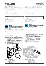
Justage des Druckkopfes:
1. Das Material kann im Drucker verbleiben.
Das Transferband kann mit dem Werkzeug durch-
gestochen werden.
HINWEIS!
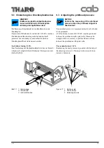
Versteifung (3) muss hochgeklappt und
arretiert sein!
2. Feststellschraube (2) um eine halbe Umdrehung lösen.
Dies reicht für eine Druckkopfverschiebung nach vorn
oder nach hinten aus.
3. Gehen Sie bei der Verstellung der Schrauben (1) wie
folgt vor:
HINWEIS!
Justage in kleinen Schritten durch-
führen (Viertelumdrehungen)!
- Durch Drehen im Uhrzeigersinn wird der
Druck-
kopf 0,5 mm pro Umdrehung nach vorn verschoben.
- Beide Schrauben (1) gleichmäßig verstellen, bis
zumindest eine Seite des Druckbildes optimiert ist.
- Anschließend die noch nicht optimierte Seite des
Druckbildes justieren.
HINWEIS!
Druckkopf nach jedem Justageschritt
kurz öffnen und wieder schließen, weil
erst dann die Verstellung vollständig
wirksam wird!
4. Festellschraube (2) nach Einstellungen festziehen.
5. Probedruck durchführen. (z.B. schwarzer Balken
über die gesamte Druckbreite)
6. Arbeitschritte zur Optimierung des Druckbildes
wiederholen, bis das Druckbild in Ordnung ist.
6
Alignings and Adjustings
6.1
Aligning the printhead
For optimum print quality, the line of heating elements on
the printhead must be parallel and aligned correctly to the
print roller. This alignment has already been performed in the
factory.
Nevertheless, it may become necessary to adjust it.
A misaligned printhead causes a poor print quality which
appears as described below :
the print image looks generally light, spotted, and
irregular; or
the print image appears uneven from one side to the other.
Adjust the printhead as follows:
1. Leave the material inside the printer.
The transfer ribbon can be pierced by the hex wrench
which is used for the adjustment.
NOTICE!
The plate (3) must be locked!
2. Loosen the locking screw (2) on the printhead by a half
turn. This will allow the required horizontal movement
of the printhead.
3. By turning the two screws (1) adjust the printhead as
follows:
NOTICE!
Carry out the adjustment in small steps
(quarter turns only)!
- By turning the screws clockwise, the printhead will
be shifted forwards by .02 in or .5 mm per turn.
- First, turn both screws (1) in the same manner until at
least one side of the print image is optimized.
- Following, adjust the screw at this side, where the
print quality is still poor.
NOTICE!
The printhead must be opened and
closed after each adjustment step to
make the change effective!
4. Tighten the locking screw (2).
5. Perform a test print, for instance a wide black line over
the whole width of the label, and review the result.
6. Repeat the steps 2 to 5 as necessary to complete the
adjustment.
Содержание A8
Страница 75: ...Index 1 00 02 29 A 8 B Anlage B Blockschaltbild Appendix B Block Diagram ...
Страница 85: ...Index 1 00 02 29 A 8 D1 Anlage D Belegungsplan Leiterplatte A8 Appendix D Layout Diagram PCB A8 ...
Страница 87: ...Index 1 00 02 29 A 8 E Anlage E Steckerplan A8 Appendix E Connector Diagram A8 ...
Страница 91: ...A 8 F4 ...


