


29
6.9
Sensors on Cylinder Z
1
3
2
4
5
6
8mm
Fig. 29
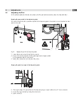
Sensors on cylinder Z
Sensor 1 Start Position
1. Loosen screw (1) of the sensor "Start Position" (3) and move the sensor so that the top edge of the sensor is on
the same level as the sensor holder.
2. Loosen screw (2) and move the sensor holder to a distance of 8 mm between top edge of the sensor and the
lower edge of the connecting ring of the cylinder like shown in the illustration.
3. Tighten screw (2).
4. Check the sensor in the applicator operation.
•
Cylinder is moved in and the pad is in start position. - LED at the sensor glows
•
The pad is not in the start position. - LED at the sensor does not glow
Sensor 2 Labelling
The position of the labelling sensor (6) is dependant on the pad assembly's weight and the mounting position. The
spring tension on the adapter bolt is dependant on these parameters and must be adjusted so that the sensor cannot
trigger unintentionally. The triggering magnet is integrated in the adapter bolt and changes position with the tension
spring.
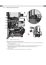
Magnet
Detection point
in sensor
Sensor
Pad free
Pad on
product
Magnet
Detection point
in sensor
Sensor
Setting Nut, black with
Cut-Out 13mm
Knurled Nut
Fig. 30
Labelling sensor principle
1.
Getting the printer and applicator into the final orientation.
2. Adjust the spring tension on the adapter bolt (4) via the black setting nut so that:
•
The adapter bolt is not pushed into the stamp assembly group during motion.
•
The sensor triggers when the pad has reached the labeling position.
3.
Turn the setting nut with an open spanner 13 mm and fix the knurled nut by holding it.
•
Turning the setting nut clockwise will increase the spring tension.
•
Turning the setting nut counterclockwise will decrease the spring tension.
4. Loosen screw (5) and move the sensor (6) so that the LED
lights up when the adapter bold is pushed into the pad
assembly.
5. Tighten screw (5).
Содержание 4214 Series
Страница 1: ...Service Manual 4214 MADE IN GERMANY Stroke Turn Applicator...
Страница 39: ...39 9 Drawings 9 2 Pneumatic Drawing Type 4214 Fig 43 Pneumatics type 4214...
Страница 40: ...40 40 9 Drawings 9 3 Labeling Position Type 4214 L Fig 44 Labeling position 4214L...
Страница 41: ...41 9 Drawings 9 4 Label Position Type 4214 R Fig 45 Labeling position 4214R...


