C-Nav Hardware Reference Guide
58
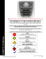
Option #5
: 19” Rack Mount
Use this adaptor if installing the C-NaviGator to a rack. The 19” Rack Mount takes up 7U of rack
space and is 12 ¼” in height. Appropriate hardware is included to secure the C-NaviGator to the
Rack Mount prior to mounting. Bolt tread size is M4 x 6mm
Figure 3-58: 19” Mounting Kit (for C-NaviGator II) / SYNIWO-6710-7CBR9
Содержание 1000
Страница 1: ...DGNSS Systems Hardware Guide www cnavgnss com ...
Страница 20: ...C Nav Hardware Reference Guide 20 Figure 2 3 C Nav Antenna Mounting Pole Dimensions ...
Страница 61: ...C Nav Hardware Reference Guide 61 Figure 3 61 C NaviGator II rev A front USB port model Outline Diagram mm ...
Страница 65: ...C Nav Hardware Reference Guide 65 Model No 3402 17 0070 Specifications ...
Страница 67: ...C Nav Hardware Reference Guide 67 Huber Suhner Lightning Protector Mounting Instructions ...
Страница 68: ...C Nav Hardware Reference Guide 68 ...
Страница 69: ...C Nav Hardware Reference Guide 69 MOXA Converters TCC 80I TCC 80I Specifications ...
Страница 70: ...C Nav Hardware Reference Guide 70 TCC 80I Dimensions Figure 4 3 Moxa TCC 80I Converter Dimensions TCC 82 ...
Страница 72: ...C Nav Hardware Reference Guide 72 Times Microwave LMR400 Coaxial Cable LMR400 Specifications ...
Страница 74: ...C Nav Hardware Reference Guide 74 ...