background image

VX709

- 1 -

Service Manual

Published by Service Dept.

Printed in Japan

Clarion Co., Ltd.

7-2, Shintoshin, Chuo-ku, Saitama-shi, Saitama 330-0081 Japan

Service Dept.:  7-2, Shintoshin, Chuo-ku, Saitama-shi, Saitama 330-0081 Japan

Tel: +81-48-601-3705   FAX: +81-48-601-3804

298-6650-00 Feb.2009

Model

This product is a lead free model.

Lead free solder is used in PWB stamped LF mark.

Please keep the following conditions when you repair.

 1. Use lead free solder.

* Koki's lead free solder S3X-55M 0.6mm

       (CLARION Parts No.642-0231-01)

* Koki's lead free solder S3X-55M 1.0mm

       (CLARION Parts No.642-0231-02)

 2. Use a nitrogen solder system.

 3. Do not use "General solder" and "Lead free solder"

together.

2-DIN DVD Multimedia Station
With CeNET & 7-inch Touch Panel
Control

( QZ-6074B-A )

Original model

Manual No.

MAX685BT(QZ-6072B-A)

298-6566-00

NOTES

*

The tuner of this unit is DSP type. When the tuner pack

is exchanged, it is necessary to adjust for S-meter etc.

The special equipment is used for an accurate adjust-

ment.

*

DSP IC(IC1) cannot be removed with an ordinary sol-

dering iron because of the pad type.

*

It is different from the adjustment display published in

the original service manual according to the connected

navigation unit.

*

Manufactured under license from Dolby Laboratories.

"Dolby" and the double-D symbol are trademarks of Dolby

To engineers in charge of repair or

inspection of our products.

Before repair or inspection, make sure to follow the

instructions so that customers and Engineers in charge

of repair or inspection can avoid suffering any risk or

injury.

1. Use specified parts.

The system uses parts with special safety features against fire

and voltage. Use only parts with equivalent characteristics

when replacing them.

The use of unspecified parts shall be regarded as remodeling

for which we shall not be liable. The onus of product liability

(PL) shall not be our responsibility in cases where an accident

or failure is as a result of unspecified parts being used.

2. Place the parts and wiring back in their original positions after

replacement or re-wiring.

For proper circuit construction, use of insulation tubes, bond-

ing, gaps to PWB, etc, is involved. The wiring connection and

routing to the PWB are specially planned using clamps to keep

away from heated and high voltage parts. Ensure that they are

placed back in their original positions after repair or inspec-

tion.

If extended damage is caused due to negligence during re-

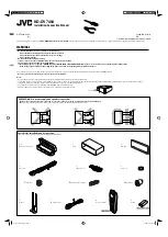
ORIGINAL SERVICE MANUAL

The base of this model is MAX685BT. This manual chiefly

publishes the difference point with the base model. Please

refer to the following service manual of the basic model.

Laboratories.

*

This product includes technology owned by Microsoft

Corporation and cannot be used or distributed without a

license from MSLGP.

*

We cannot supply PWB with component parts in prin-

ciple. When a circuit on PWB has failure, please repair it

by component parts base. Parts which are not mentioned

in service manual are not supplied.

*

Specification and design are subject to change without

notice for further improvement.

Summary of Contents for VX709

Page 1: ...nstructions so that customers and Engineers in charge of repair or inspection can avoid suffering any risk or injury 1 Use specified parts The system uses parts with special safety features against fire and voltage Use only parts with equivalent characteristics when replacing them The use of unspecified parts shall be regarded as remodeling for which we shall not be liable The onus of product liab...

Page 2: ...you apply power to the unit 10 Cautions in checking that the optical pickup lights up The laser is focused on the disc reflection surface through the lens of the optical pickup When checking that the laser opti cal diode lights up keep your eyes more than 30cms away from the lens Prolonged viewing of the laser within 30cms may damage your eyesight 11 Cautions in handling the optical pickup The las...

Page 3: ...r pin 56 INES ON O Inner escutcheon illumination ON signal output pin 57 TV MODE O TV MODE signal output pin 58 OSD RST O Reset pulse output for the on screen dis play IC pin 59 XM RX IN XM serial data input pin 60 XM TX O XM serial data output pin 61 DVD TX O Serial data output to the DVD mechanism pin 62 DVD RX IN Serial data input from the DVD mecha nism pin 63 W REMCOM IN Wired remote controll...

Page 4: ...se pin 19 NU Not in use pin 20 NU Not in use pin 21 NU Not in use pin 22 NU Not in use pin 23 NU Not in use pin 24 NU Not in use pin 25 NU Not in use pin 26 D VSS Digital ground pin 27 D VDD Positive voltage supply for the digital sec tion pin 28 REQ O O Request signal output pin 29 NU Not in use pin 30 NU Not in use pin 31 NU Not in use pin 32 NU Not in use pin 33 P ON 2 O Power ON signal output ...

Page 5: ...e supply voltage pin 28 OE IN Output enable signal input pin 29 D 0 I O Data input output pin 30 D 8 I O Data input output pin 31 D 1 I O Data input output pin 32 D 9 I O Data input output pin 33 D 2 I O Data input output pin 34 D 10 I O Data input output pin 35 D 3 I O Data input output pin 36 D 11 I O Data input output pin 37 VDD Positive supply voltage pin 38 D 4 I O Data input output pin 39 D ...

Page 6: ...22 20 19 17 17 6 6 18 26 25 30 32 27 28 24 23 8 4 4 29 4 20 30 17 17 34 31 33 6 6 18 1 2 3 3 2 9 8 10 11 12 4 4 10 13 12 14 16 6 6 21 4 63 6 64 58 50 59 52 55 56 57 51 8 30 18 18 54 53 46 15 60 6 6 6 7 5 4 61 62 Rear cover of escutcheon EXPLODED VIEW PARTS LIST Main section ...

Page 7: ...OLDER 1 34 312 0492 00 SIDE CHASSIS L 1 35 USB PWB 1 36 816 3028 50 FLAT WIRE 1 37 335 0833 01 LEAD HOLDER 2 38 855 0645 50 EXTENSION LEAD 1 39 331 4501 00 CONNECT HOLD M 1 40 714 3004 8B MACHINE SCREW M3x4 2 41 020 3053 00 DC MOTOR 1 42 780 2614 50 SCREW M2 6x14 LOCK 2 43 855 0613 52 USB CABLE 1 44 855 5436 51 RCA PIN CORD 1 45 345 3799 20 RUBBER PART 1 46 347 8527 00 SHADE 1 47 312 0494 00 LOWER...

Page 8: ... 0041 00 MICROPHONE 1 24 345 6130 00 RUBBER SHEET 2 25 039 3226 00 FPC 1 26 013 6312 50 SWITCH 10 27 001 7097 90 DIODE 10 28 060 4017 90 IR RECIEVER 1 29 778 2004 01 PAD SCREW M2x6 9 30 001 7098 90 DIODE 2 31 074 2236 65 SOCKET 15P 2 32 716 1468 01 SCREW M2x2 5 2 33 060 8084 00 BLUETOOTH ANT 1 34 331 4498 00 ANT HOLDER 1 35 347 8475 00 FILM 1 36 001 7103 90 DIODE 1 37 347 8476 00 FILM 1 38 039 322...

Reviews: