background image


USER 
MANUAL 


The

 CM2 

SIDESCAN 
SONAR 
SYSTEM


(All configurations except 
those using MaxPro software) 


Issue 3.6 
 
©  C-MAX Ltd 2008


Содержание CM2

Страница 1: ...USER MANUAL The CM2 SIDESCAN SONAR SYSTEM All configurations except those using MaxPro software Issue 3 6 C MAX Ltd 2008 ...

Страница 2: ...CM2 Sidescan Sonar User Manual Version 3 6 2008 ii ...

Страница 3: ...1 Survey Plan Line Spacing Line Direction 5 Operating the Towfish 13 Pre launch Check Launch Flying the Towfish Recovering the Towfish Action if the Towfish Fouls 6 Operating Guidelines 16 7 Notes for the Helmsman 17 Navigation Steering Emergency Actions 8 Towfish Commands 18 Towfish Command Set Bottom tracking Up and Down Mute On or Off Shallow Mode On or Off Gain Hold On or Off Gain Up or Down 9...

Страница 4: ...shooting 26 14 Interfaces 28 Towfish Tow Cable STR C Shell C Case 2 C Case SE 15 Specifications 30 Towfish STR C Shell C Case 2 C Case SE Tow Cables Sections 16 22 cover optional accessories 16 CM2 WIN 300 Winch 33 17 SK172 and SK172E Winches 37 18 Wing Depressor 39 19 Pulleys and Counting Pulleys 41 20 Polemount Bracket 43 21 USBL Transponder Bracket 44 22 Towfish Sensors 45 23 ROV and AUV Config...

Страница 5: ...NG NAV DATA SOURCES OR ECHO SOUNDERS MUST BE CHECKED BEFORE CONNECTION IS MADE TO THE SERIAL PORT OF ANY ACQUISITION PC OR C CASE THE GROUND LEVELS MUST BE EQUAL OR FLOATING IF NOT THEN THE INTERNAL CPU PCB MAY BE DESTROYED AND DAMAGE SO CAUSED IS NOT COVERED BY WARRANTY DO NOT ALLOW THE TOWFISH TO STRIKE THE BOTTOM OR OBSTRUCTIONS THE TOWFISH SINKS WHEN THE BOAT TURNS OR SLOWS USE GLOVES TO HANDL...

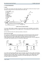
Страница 6: ...le receives the echo data and other information such as the towfish altitude and sends commands to the towfish The primary type of top end unit for the CM2 system is the Sonar Transceiver or STR As well as communicating with the towfish the STR communicates with the PC that acquires records and displays the sonar image Communication with the PC is via the STR s USB interface Sonar Transceiver STR ...

Страница 7: ...proof IP67 unit complete with waterproof connectors The STR can be quickly fitted or removed C Shell Panel and Connectors The C Shell includes a 4 way USB hub that can be used to house a dongle for the acquisition software The C Shell can also be specified with an integral GPS receiver the GPS output is fed to the hub for transmission to the external USB link Version 3 6 2008 3 ...

Страница 8: ...to the earlier version that ran MaxPro under DOS It is an all in one data acquisition unit with an integral PC designed for use in the exposed environment of an open boat It uses MaxView or third party acquisition software running under Windows C Case 2 Panel and Connectors Version 3 6 2008 4 ...

Страница 9: ...2 tow cables use a single pair of electrical conductors to carry both data and power There are two types of tow cable offered with the CM2 Soft cable is intended for shallow work where the cable can be hauled and veered manually The alternative is steel armoured cable handled by a winch Various diameters of steel armoured cable are available the smallest being 4 7mm used on the CM2 WIN 300 winch A...

Страница 10: ...able or deck cable to the STR Connect a navigation data cable to the PC if required As GPS and other sources of navigation data often output via an RS232 serial connection and as serial ports are becoming less common on PCs this connection may require the use of a serial to USB converter Note that if a CM2 C Shell fitted with an STR is being used the GPS data from the C Shell s optional internal G...

Страница 11: ...e the maximum off axis angle of the cable Also the winch should be located directly ahead of the pulley to minimize the tilting of the pulley and side force on the pulley rim The winch mounting must be able to withstand the shock of the towfish striking the bottom The mounting footprint of the CM2 WIN 300 winch is shown in Section 16 Securing a soft Tow Cable if used Make sure that enough cable is...

Страница 12: ...the towfish being careful to align the connector correctly It is good practice to keep this plug clean and occasionally and only very lightly grease the rubber sleeves of the pins with the silicone grease provided Attach the towing bail using the breakable safety washer and the M6 cap screw with captive washer Use the 5mm hex key provided to tighten this screw The breakable washer is designed to f...

Страница 13: ...ck Select menu If some other acquisition software is installed instead of MaxView the towfish can be started using that software When the towfish is commanded to start the green Trigger indicator on the STR should light continuously whilst the Start Towfish dialog displays the Energizing message This message should be automatically replaced after a short period by Connecting The Energizing message...

Страница 14: ...lace one hand briefly on the face of one of the transducers This should result in an increase in signal on the appropriate side of the waterfall display for the time that the hand is that position at least until the automatic gain control reduces the signal Then test the other side in the same way Note that although this is called a rub test no rubbing action is necessary the signal is induced cap...

Страница 15: ...e towfish because the image when received is compressed and also the steep angle results in poorer shadow information The quality is also reduced at the extremity of the range primarily because of beam spreading Survey lines should therefore be spaced with sufficient overlap e g 75m when working with 100m range setting to ensure complete coverage Overlap is also necessary to compensate for course ...

Страница 16: ... is easier to survey along lines of approximately constant depth rather than to be constantly heaving and veering tow cable to keep the towfish at a suitable altitude Finally the wind direction may be the controlling factor Waves running across rather than in the same direction as the survey line will cause a spiralling movement of the tow cable and oscillation of the towfish track This will have ...

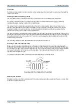
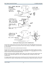
Страница 17: ...ow dots on the depression adjuster cam Adjusting the Transducer Depression Angle Check that the tow cable connector is firmly home and that the bail is correctly attached to the towfish Check that the tow cable is clear and free from twists and that the winch is powered and ready to run Note that the automatic gain adjustment starts as soon as the towfish is switched on Version 3 6 2008 13 ...

Страница 18: ...ot necessarily the true altitude at this stage is shown in MaxView s sonar parameters or equivalent and may also be also marked on the display by a pair of lines overlying the initial bottom echoes Check that the altimeter is locked on the initial bottom echo not on the surface echo nor is left in a neutral position IF THE ALTIMETER INITIALLY FAILS TO LOCK ON TO THE BOTTOM CORRECTLY USE THE FORCE ...

Страница 19: ...rom speed over the ground or GPS indicated speed Low over the ground speeds give more scans per metre of travel and a correspondingly better image resolution Sometimes however a higher speed will give a steadier course Caution the towfish will sink towards the bottom whenever the towing vessel slows or turns Recovering the Towfish Slow to 2 to 4 knots before the towfish hits the wake Watch for the...

Страница 20: ...gher tow speeds are ok for LF 100kHz operations e g up to 6 knots Use lower tow speed for HF 325kHz operations e g 4 knots Use lowest tow speed for EF 780kHz short range operations e g 3 knots Low speed gives more pings on each target and gives greater towfish depth for any particular tow cable length High speed makes it easier to keep the towfish on a straight course Overlap survey tracks to give...

Страница 21: ...helmsman even though the heading may need to be trimmed occasionally Remember that the towfish follows the stern particularly when the tow cable is short and is therefore affected by rudder movements as well as by course deviations At the end of the survey line the helmsman must warn the sonar operator before turning and must not turn sharply or the towfish could strike the bottom Emergency Action...

Страница 22: ...tion itself instead of at the first bottom echo and the indicated altitude is zero Gain Hold Off or On Gain Hold allow the automatic gain to be inhibited fixing the gain profile as it was when Gain Hold was selected Normally the only reason to disable the automatic gain is if the image of a certain target such as a wreck needs to be observed without the gain slowly changing If the gain profile is ...

Страница 23: ...mid water objects may appear in the water column on one or both sides depending on whether they are to one side of the towfish but still nearer to the towfish than to the bottom or are directly below the towfish Highlights and Shadows The towfish sees most of the bottom in its view at quite a low angle as little as 5º at the outer regions This means that the sonar picture normally includes both hi...

Страница 24: ...ut excessive heave motion transmitted down the tow cable Any erratic motion of the towfish will transfer to the image Roll oscillations may produce light and dark banding alternating between port and starboard sides Turning stretches the image on one side and compresses the other If the towfish is near the surface it may pick up reflections from the surface waves This can reduce the maximum range ...

Страница 25: ...very 20 deployments whichever is more frequent spray chain lube or WD40 or similar into the cable terminator Insert a small screwdriver or spike between the black PVC sheath and the tow cable then insert the tube extension of the chain lube dispenser alongside the screwdriver and inject enough lubricant to ensure that the internal strands of the cable hidden by the sheath are protected from corros...

Страница 26: ...ed in purpose designed containers Internally padded shipping storage cases can be supplied for all the system components On the optional CM2 or SK172 winches tape or strap the tow cable to prevent it unreeling from the winch drum Ensure that all equipment particularly the STR is dry before packing Keep the empty cases closed whilst the system is in use so that they do not accumulate condensation V...

Страница 27: ...rs to the keel Disassembled Towfish Remove the two M5 socket cap head screws at the forward end of the keel This is easier if the towfish tube is pressed down on the keel to keep pressure off the screws Push the tube forward and then disconnect the two transducer connectors Completely separate the tube assembly from the keel transducer assembly The rear bulkhead is now free to be extracted from th...

Страница 28: ...sducer To replace one or both of the acoustic transducers do not separate the rear bulkhead from the towfish tube Remove the tube assembly as described in the previous section Remove the two temporary cable ties and then lift out the pair of transducers still hinged together with the hinge rod Slide out the hinge rod Be careful to retain the adjuster components on the rod They must be grouped at t...

Страница 29: ...then remove the two M3 nuts holding the black anodised cover from the connector panel This reveals the printed circuit board mounted on the back of the connector panel that carries the 20x5mm 10A fuse in the DC supply to the STR This PCB also includes the 12V regulator for the fan and power LED Servicing the C Case 2 To gain access to the internal parts of the C Case 2 remove the eighteen M3 screw...

Страница 30: ... free from oil or grease Clean with mild detergent Try greater towfish altitude Check system performance in a known environment Image shows unexpected patterns on outer zones If the sea surface is rough and the bottom is smooth then suspect interference from surface echoes Try setting the transducer depression angle to low 20º Image shows spots or other interference Temporarily mute the towfish to...

Страница 31: ...heck the supply voltage and polarity Check the operation of the remote control pendant using an ohmmeter between the COMMON and IN and OUT contacts Other troubleshooting advice If further advice is required consult your local representative or the Factory Version 3 6 2008 27 ...

Страница 32: ...er requirements C Shell Interface PC link MIL C 5015 size 14 threaded 4 way bulkhead connector Pin A gnd pin B 5V pin C data pin D data USB1 1 or 2 0 Tow cable or winch deck cable MIL C 5015 size 10 threaded 2 way bulkhead connector Sockets A and B polarity not significant Power input MIL C 5015 size 10 threaded 2 way bulkhead connector Pin A ve pin B gnd see C Shell Specifications for power requi...

Страница 33: ...ead connector Pin A gnd D type skt 5 pin B RX D type skt 2 pin C TX D type skt 3 pin D N C Counting pulley port RS232 serial port MIL C 5015 size 14 threaded 6 way bulkhead connector Skt A gnd D type skt 5 skt B RX D type skt 2 skt C TX D type skt 3 Skt D DTR D type skt 4 skt F RTS D type skt 7 PC link internal MIL C 5015 size 14 threaded 4 way bulkhead connector Pin A gnd pin B 5V pin C data pin ...

Страница 34: ...m altitude resolution Safety features Weak link breaks to give tail first towing Sensor options Heading pitch roll depth 0 200m other depth ranges available Construction Stainless steel no aluminium Towfish dimensions and weights 1 24m length 17 9kg in air 12 1kg in seawater DF 17 1kg in air 11 3kg in seawater EDF Towfish temperature range 10 to 45ºC operating 20 to 50ºC non operating STR Specific...

Страница 35: ...ingle unit It is designed to run MaxView or third party acquisition software CPU 1GHz 256MB RAM 40GB HDD Interfaces Tow cable navigation counting pulley parallel printer USB for post survey data export AC DC power either may be used Dimensions mm and weight 620W x 495D x 225H 13kg Power 115 230V 50 60Hz 100W max 80W typical 24V DC option 4A max 3A typical Environment 0 to 45ºC 10 to 80 RH 5G opera...

Страница 36: ... resistance 200ohm max Tow cable diameter options 11 4 8 2 6 4 or 4 7mm stainless steel armoured 8mm soft polyamide reinforced PU sheathed Custom cables also available also suits some legacy cables Tow cable terminator weak link breakable washer 75kgf nominal actuation tension actuates to reverse tow the towfish Version 3 6 2008 32 ...

Страница 37: ...ended to slip under excessive load The slipping torque is determined by a pair of internal disc springs The pre load on these springs is adjusted by the four hex headed clutch tension screws on the flange nearest the motor plate If the clutch is slipping under normal use tighten these by rotating them all one half turn clockwise All four screws must be rotated an equal amount As a guide with the c...

Страница 38: ...or the control pendant are as follows Pin E White button wind out Pin H Common 24v Pin A Black button wind in Winch Specifications Capacity 300m of 4 7mm tow cable Power 24V at up to 100A peak 50A peak if soft start fitted Construction Stainless steel Winch dimensions mm and weight 45OW x 350D x 300H 47kg when fitted with 300m cable 63kg packed in transit case with control pendant power cables etc...

Страница 39: ... remove the cable from the drum Feed the new cable through the slot in the drum Attach a cable grip to the tow cable to prevent it being withdrawn in normal use several cable turns must always be present on the drum because the cable grip is not intended to hold full towing forces Attach the 2 insulated wires to the pair of wires projecting from the slip ring unit insulating the joints with heatsh...

Страница 40: ...g fan and motor temperature alarm These are all accessible beneath the motor cover Note that some of the components may be absent from early units The motor cover is released by removing the three M4 screws at its base then lifting it clear A soft start controller is mounted on the inside of this cover except early units and care must be taken not to pull on any of the attached wires CM2 Winch Cir...

Страница 41: ...ring for the drum Remove the screws securing the drum flange and lay the flange aside Note how the tow cable is routed Reach into the drum loosen the central sealing gland and then withdraw the coaxial signal cable that extends from the end of the tow cable Replace the tow cable by the reverse of the above procedure first inserting the tow cable in the slot in the winch drum Identify the two condu...

Страница 42: ...t the end bearing plate Rotate the winch several times to position the cable firmly around the drum Then seal the cable exit slot using silicone rubber compound The control pendant connections are as follows Pin E White button winding out Pin H Common 24v Pin B Black button winding in Version 3 6 2008 38 ...

Страница 43: ...load on the winch motor can be eased simply by reducing tow speed whilst heaving an option that is not available with static ballast Fitting the Wing and Tail to the Towfish Attach the wing to the towfish as shown in the illustration with the wing clamp directly in front of the towfish handle assembly There should be no gap between the towfish handle assembly and the wing clamps Use the four 20mm ...

Страница 44: ...Wing is fitted Refer to the illustration for the effect of the wing hydrodynamic down force on the towfish depth For any particular depth a shorter length of cable can be used with reduced layback Depth Performance with and without Wing Depressor Note also the increase in tow cable tension Extra tension increases the power consumption of the winch if used whilst hauling in the cable and care must ...

Страница 45: ...inforced cables and with steel armoured cables up to 11 5mm diameter All types may be used as simple pulleys or with addition of a Pulley Sensor and cable are suitable for conversion to counting pulleys Counting Pulley Type L Cable Guides If a pulley is to be used with a polyurethane sheathed tow cable there may be circumstances where the stickiness of the cable would cause it to ride up on the ri...

Страница 46: ...with one magnet Types O and S or two magnets Type L so the rotation can be detected at intervals equivalent to half metre intervals at the circumference The pulley sensor is connected to a PC s serial port via a counting pulley deck cable Depending on the PC the deck cable may need to be terminated in a serial to USB converter The PC may be the same PC that is used with an STR or may be a navigati...

Страница 47: ...he image from the beam passing under the hull can be affected by reflection from the hull resulting in multipart distortion An alternative to rigid mounting is towing from the bow or from the beam Fitting the Polemount Bracket The positioning of the overside pole and its mounting to the hull is outside the scope of this manual Fit the CM2 polemount bracket to the lower end of the pole as shown in ...

Страница 48: ...r If the transponder is simply secured to the terminator using duct tape it may generate eddy currents and oscillate these oscillations may be enough to fracture the bail arms eventually The USBL bracket also holds the transponder at an angle so that it is closer to pointing at the USBL transceiver array fitted to the towing vessel Fitting the USBL Bracket to the Tow Cable Terminator Fitting the b...

Страница 49: ...ay be already installed in the towfish when delivered or may be retrofitted in the field To fit the sensor first open the towfish to expose the towfish PCB See the section on Replacing the Towfish PCB for advice on opening the towfish Attach the Heading Sensor Extension to the towfish PCB as shown in the illustration Then attach the Heading Sensor itself to the extension The heading sensor cable c...

Страница 50: ...s the bulkhead to be replaced The bulkhead and towfish PCB should be returned to C MAX for modification See the section on Replacing the Towfish PCB for advice on opening the towfish The depth sensor cable connects to J8 on the towfish PCB The depth sensor specification is in Section 15 There is no provision for zeroing the depth indication as it is not intended to be used with the same accuracy a...

Страница 51: ...tem An STR and PC at the surface complete the system The bulkhead on the end of the electronics bottle is held in place by a retainer instead of the fin keel assembly as on the towfish but otherwise much of the description of the operation and maintenance of the towed system in this manual is also applicable to the ROV system Note that the towfish mute command is particularly useful on an ROV allo...

Страница 52: ...al loss nor for any failure caused by improper use mishandling or unauthorised attempts at repair nor for cosmetic or other damage which may reasonably be classed as normal wear and tear In particular if it is apparent from the condition of the CM2 WIN 300 winch that it has been abused or overheated then repair or replacement of winch components will not be covered under this warranty Fault Report...

Отзывы: