C-COR.net FlexNet E7 Скачать руководство пользователя страница 95

Rev F

Reference Tables

C-7

C

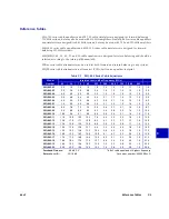
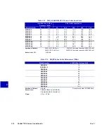
Table C.3 SEQ-750 Series Cable Equalizers

dB of cable 

equalized at 

highest 

frequency

Insertion Loss in dB at Frequency (MHz)

Model Number

54

70

80

222

350

450

550

650

750

SEQ-750-02

2.0

2.0

2.0

1.8

1.4

1.3

1.3

1.2

1.0

1.5

SEQ-750-03

3.0

2.8

2.7

2.4

1.9

1.7

1.5

1.3

1.0

2.5

SEQ-750-04

3.9

3.9

3.8

3.1

2.4

2.0

1.7

1.4

1.0

4.0

SEQ-750-05

4.9

4.6

4.5

3.5

2.9

2.3

1.8

1.4

1.0

5.0

SEQ-750-06

5.9

5.7

5.6

4.2

3.3

2.7

2.0

1.5

1.0

6.5

SEQ-750-07

7.0

6.8

6.6

5.0

3.6

2.8

2.0

1.6

1.0

8.0

SEQ-750-08

8.0

7.9

7.6

5.5

4.2

3.3

2.5

1.8

1.0

9.0

SEQ-750-09

9.0

8.8

8.6

6.3

4.8

3.8

2.7

2.0

1.0

10.5

SEQ-750-10

9.8

9.4

9.2

6.7

5.0

3.8

2.8

2.0

1.0

12.0

SEQ-750-11

11.0

10.5

10.2

7.5

5.5

4.2

3.0

2.0

1.0

13.5

SEQ-750-12

11.8

11.3

11.0

8.1

6.0

4.6

3.3

2.2

1.0

14.5

SEQ-750-13

12.9

12.4

12.2

8.9

6.6

5.1

3.7

2.5

1.0

16.0

SEQ-750-14

14.0

13.5

13.2

9.7

6.9

5.3

3.8

2.5

1.0

17.0

SEQ-750-15

14.9

14.3

13.9

10.1

7.5

5.8

4.3

2.6

1.0

18.5

SEQ-750-16

15.8

14.9

14.5

10.5

8.0

6.1

4.4

2.7

1.0

20.0

SEQ-750-17

16.8

16.0

15.6

11.3

8.2

6.2

4.4

2.6

1.0

21.0

SEQ-750-18

17.9

17.1

16.6

11.9

8.6

6.6

4.6

2.6

1.0

22.4

SEQ-750-19

18.8

17.8

17.4

12.3

9.1

6.9

4.8

2.7

1.0

23.7

SEQ-750-20

19.8

19.0

18.5

13.2

9.5

7.2

5.0

2.8

1.0

25.0

SEQ-750-21

20.8

19.8

19.3

13.4

10.0

7.5

5.2

2.9

1.0

26.3

SEQ-750-2-2

2.8

2.8

2.8

2.5

2.3

2.2

2.1

2.1

2.0

1.1

SEQ-750-4-2

4.5

4.4

4.3

3.6

3.1

2.8

2.5

2.2

2.0

3.3

SEQ-750-4-3

5.5

5.4

5.3

4.7

4.1

3.8

3.5

3.2

3.0

3.3

SEQ-750-5-5

8.9

8.6

8.6

7.6

6.9

6.3

5.8

5.4

5.0

5.0

Passband Flatness:

±0.3 dB

Document number: 600563 Rev H

Return Loss I/O:

18/16 dB

Содержание FlexNet E7

Страница 1: ...14 238 4065 P O Box 10 265 1301 AG Almere The Netherlands Tel 31 36 546 1111 Fax 31 36 536 4255 www c cor net B R O A D B A N D C O M M U N I C A T I O N S P R O D U C T S 700 Series Line Extenders E7...

Страница 2: ...Introduction fm Page 10 Monday April 1 2002 12 43 PM...

Страница 3: ...B R O A D B A N D C O M M U N I C A T I O N S P R O D U C T S FlexNet E7 and E629 E q u i p m e n t M a n u a l...

Страница 4: ...and MobileFORCE are registered trademarks and lumaCOR Optiworx COR Convergence and COR ISMS are trademarks of C COR net Corp All other brand and product names are trademarks or registered trademarks...

Страница 5: ...A Technical Support Contact Technical Support when you need assistance with installed products Phone Technical Support Hotline 888 827 2267 24 hours a day 7 days a week Or call Monday through Friday 8...

Страница 6: ...vices Technical Publications C COR Technical Publications welcomes your suggestions and assistance in identifying any errors inaccuracies or misleading information Please reference the document number...

Страница 7: ...htening 3 16 Chapter 4 Configuration 4 1 Power Supply Configuration 4 1 Power Supply Setup 4 1 Voltage Testing 4 2 Calculating Balancing Carrier Levels 4 5 Temperature Compensation 4 5 Forward Balanci...

Страница 8: ...rams B 1 Appendix C Reference Tables C 1 Use Of Reference Tables C 1 When the Equalization Value is Known C 1 When Preceding Cable Loss and Internal Equalization are Known C 2 Installing Plug in Acces...

Страница 9: ...xNet 700 Series Line Extender document conventions compliance statements and suggested tools and materials required when working with the E7 Line Extender Overview page 1 2 Document Conventions page 1...

Страница 10: ...r cord designed to operate in closed environments such as apartment buildings E77 For specific E7 Line Extender characteristics refer to the C COR customer specification sheet for the particular line...

Страница 11: ...H I G H H I G H V O L T A G E V O L T A G E DANGER H I G H H I G H V O L T A G E V O L T A G E LINE EXTENDER x ATTENTION WARNING Dorem et lorel en sabad deriddem lireeden ilfarde e huire le fjor desi...

Страница 12: ...esignator Options Part Number E7 x x x x xx x x x x x E7 FlexNet 700 Series PHD Line Extender Series 0 21 dB PHD Spacing 1 28 dB PHD 2 30 dB PHD 3 33 dB PHD 5 32 dB PHD 7 35 dB PHD C 750MHz Bandwidth...

Страница 13: ...this device to be in violation of Part 76 of the FCC Rules voiding the user s authority to operate the equipment CE Compliance This device conforms to the protection requirements of Council Directive...

Страница 14: ...al Needlenose Pliers Jumper removal Return kit installation Soldering Iron small Return kit installation IC extractor tool Return kit installation in E629 Heat gun or approved torch and heatshrink tub...

Страница 15: ...C bolts washers and shims Wall mounting Two diplex filters P N 162198 01 Return kit installation in E629 Extension Mounting Brackets EMBs 3 2 or 6 inch 8 or 15cm length with mounting hardware P Ns 172...

Страница 16: ...1 8 FlexNet 700 Series Line Extender Rev F 1...

Страница 17: ...for FlexNet 700 Series Line Extenders Figure 2 1 E7 Line Extender w 90Vac High Efficiency Power Supply page 2 2 Figure 2 2 E7 Line Extender w Linear Power Supply page 2 3 Figure 2 3 E75 862MHz ALC Lin...

Страница 18: ...ne Extender w 90VAC High Efficiency Power Supply1 1 RF module faceplate has fingerstock attached for grounding purposes Do not block contact with power supply when closing housing cover 2 3 7 8 10 11...

Страница 19: ...CING dB REV ALC SENSITIVITY REVERSE EQ ALC MAN B T P RAW DC T P MODULE HOLD DOWN MODULE HOLD DOWN MODULE HOLD DOWN ALC PILOT MHz SER NO PORT 3 PORT 1 THRU POWER FUSE FORWARD PAD FORWARD EQ INTERSTAGE...

Страница 20: ...ender with Integrated Power Supply PORT 1 MODULE HOLD DOWN MODULE HOLD DOWN MODULE HOLD DOWN REV OUTPUT TP FWD EQ FWD PAD P S FUSE LINE FUSE ALC ALC SENSITIVITY REV EQ REV PAD MAN 24V DC TP INTERSTAGE...

Страница 21: ...ddem lireeden ilfarde e huire le fjor desi Dorem et lorel en sabad deriddem lireeden ilfarde e huire le fjor desi THRU POWER FUSE MAIN FUSE SER NO MHz SPACING PORT 1 PORT 3 FORWARD PAD MODULE HOLDDOWN...

Страница 22: ...2 6 FlexNet 700 Series Line Extender Rev F 2 Figure 2 5 E73 Line Extender w 117VAC Linear Power Supply x 16 25 2 3 13 13 5 4 1 7 8 10 11 6 22 13 14 20 19...

Страница 23: ...Rev F Physical Identification 2 7 2 Figure 2 6 E629 Line Extender 19 4 5 3 21 17 20 14 13 13 16...

Страница 24: ...e a 25dB label 8 PORT 3 Access to the Port 3 centerseizure screw 9 ALC SENSITIVITY Adjustment of the line extender output when the line extender is operating in ALC mode This has no affect when the li...

Страница 25: ...nable or disable TLC MAN provides a constant gain TLC causes the line extender to monitor temperature to maintain preselected output levels TLC setting requires appropriate setting of the CABLE SELECT...

Страница 26: ...2 10 FlexNet 700 Series Line Extender Rev F 2...

Страница 27: ...3 16 Preparing for Installation To inspect the housing 1 Ensure that the following are included with each housing two 2 mounting hardware kits P N HB0214 each consisting of one strand clamp one lock...

Страница 28: ...et on the housing base b Inspect the metal mesh gasket on the lid c Be certain the gaskets are well seated and unbroken Note The rubber gasket can be replaced If the metal mesh is damaged the housing...

Страница 29: ...placement on page 6 2 beginning with Step 4 for instructions on installing an RF module b If desired install plug in accessories Installing accessories at this point is often more convenient than afte...

Страница 30: ...ptive cover bolts and open lower the cover Figure 3 3 Housing Lid Bolt Loosening Sequence Housing Mounting Depending on the requirements of the system the E7 Line Extender can be mounted in any one of...

Страница 31: ...rand but is still free for adjustment 4 Position the housing at a location on the strand that is accessible for attaching cables and performing maintenance and balancing and that complies with all loc...

Страница 32: ...bolts against the EMBs 2 Attach the strand clamp assemblies to the EMBs with the 1 inch long clamp bolts and washers see Figure 3 5 3 Hoist the housing to the strand and hang it in position 4 Tighten...

Страница 33: ...ch Strand or Smaller Strand Clamp Orientation for 5 16 inch Strand or Larger Strand Clamp 1 4 inch Strand 1 2 inch EMB Bolt Lock Washer O Ring retaining Extension Mounting Bracket Top Strand Clamp Bos...

Страница 34: ...to Figure 3 6 on page 3 9 for the location of the wall mount bosses Use a 9 32 inch 7 mm diameter drill for inch diameter bolts 4 Select appropriate length 1 4 20UNC mounting bolts not supplied washe...

Страница 35: ...Rev F Housing Instructions 3 9 3 Figure 3 6 Wall Mounting with Wall Mount Bosses Wall Flat Washer Mounting Bolt Wall Mount Boss Lock Washer 9 0 in 22 86cm Wall Mount Bosses...

Страница 36: ...32 inch 7mm diameter drill for 1 4 inch diameter bolts 5 Select appropriate length 1 4 20UNC mounting bolts nuts not supplied washers and lock washers to allow a threaded bolt length of 1 4 to 3 8 inc...

Страница 37: ...ll Mounting with EMBs Wall Mounting Bolt Top Strand Clamp Boss Extension Mounting Bracket 1 2 inch EMB Bolt 3 2 inch 8cm EMB P N 172187 01 6 inch 15cm EMB P N 172187 03 Lock Washer Flat Washer Nut Loc...

Страница 38: ...the boot is long enough to cover the cable entry port insert and the entire connector The boot must also extend at least 2 inches 5cm beyond the back nut Slide the boot onto the cable and away from th...

Страница 39: ...es 2 71cm and 3 30cm to avoid unintentional signal grounding Figure 3 10 Cable Connector Assembly 5 Apply anti seize compound to threads and O ring Do not use spray lubricant CAUTION Do not use feed t...

Страница 40: ...end of the cable shield bottoms against the main nut d Thread tighten and torque the cable connector assembly according to specifications supplied by the manufacturer Hold the cable firmly in positio...

Страница 41: ...r and cable entry port or if using heatshrink slide each heatshrink boot over the entire connector and cable entry port Heat the boot to shrink it securely around the insert connector and cable as spe...

Страница 42: ...sequence finally torquing to between 35 and 40 in lbs 4 0 and 4 5 N m with a torque wrench The lid should now seat evenly and compress the rubber gasket to create a weatherproof seal 5 Install testpoi...

Страница 43: ...ly Configuration Power Supply Setup Refer to Fuse Brass Shorting Bar Slug Replacement on page 6 1 for all fuse removal and installation procedures To set up the power supply 1 Open the housing Refer t...

Страница 44: ...supply rquires the use of Table 4 3 and Table 4 4 Refer to the instrucitons that follow based on your particular powering option To test a 117VAC linear power supply Measure the B AC Ripple and Rever...

Страница 45: ...heck cable plant powering MAIN FUSE or THRU POWER FUSE3 inputs left fuseclip 3 Not applicable to units with a 117VAC linear power supply See Table 4 2 If power is acceptable at the centerseizure screw...

Страница 46: ...ltage is greater than 35VDC and the selector switch is in the lowest position replace the RF module 3 Measure the B AC Ripple and Reverse B if applicable and compare to the range shown in Table 4 4 a...

Страница 47: ...orward High Balancing Carrier level dBmV LH System Output Level at the High Bandedge Frequency dBmV LL System Output Level at the Low Bandedge Frequency dBmV FH System High Bandedge Frequency MHz FL S...

Страница 48: ...erature compensated forward balancing carrier levels for Forward Balancing or Forward Field Testing 4 Optional Repeat Steps 2 and 3 for the return balancing carriers Use these temperature compensated...

Страница 49: ...ss dB at 68 F 20 C Temperature C Temperature F TCV 0 0 dB TCV 3 0 dB TCV 1 0 dB TCV 1 5 dB TCV 2 0 dB TCV 2 5 dB TCV 1 5 dB TCV 1 0 dB TCV 0 5 dB TCV 0 5 dB 30 130 110 90 70 10 23 7 9 11 17 19 21 48 2...

Страница 50: ...ccessory locations To balance the forward path 1 Determine the System Forward High and Low Balancing Carrier Levels If bandedge carriers are used for balancing copy the E7 Line Extender bandedge carri...

Страница 51: ...able loss preceding the line extender in dB at the highest system frequency For 10dB or less preceding cable loss set the CABLE SELECT Switch to 6dB for greater than 10dB set to 15dB Figure 4 2 Simpli...

Страница 52: ...tion Value is Known on page C 1 d If necessary remove the accessory or stripline from the STATION FWD EQ area and install the selected cable equalizer or cable simulator 6 Attenuate the RF output port...

Страница 53: ...ancing Carrier Level If Temperature Compensation was used balance in ALC mode for the levels calculated before Temperature Compensation Values were determined c Record both forward balancing carrier l...

Страница 54: ...er the single person and the two person return balancing procedures These procedures assume the forward balancing requirements of Forward Balancing Requirements on page 4 8 are met When balancing the...

Страница 55: ...ss Standard sweep equipment also has a noise ingress feature that can be used for troubleshooting This displays the noise seen in the headend Tech Note TD0079 provides the generalized procedure using...

Страница 56: ...culate the Equalization Value Using the appropriate table in Appendix C select an MEQ plug in accessory that has a tilt as close to the Equalization Value as possible For a full explanation of the sel...

Страница 57: ...ignal levels of both return balancing carriers at the Port 1 and Port 3 external testpoints and record these levels on the FlexNet 700 Series Line Extender Data Sheet 6 Close the housing and replace t...

Страница 58: ...RF module Remove the faceplate to expose the circuit board 3 Refer to the appropriate procedure in Installing the Kits on page 4 17 for your particular return upgrade kit CAUTION Modifications or alt...

Страница 59: ...of the return hybrid Align the pins of the return hybrid with the holes on the motherboard Firmly press the return hybrid down to the motherboard 4 Insert the two hybrid mounting screws supplied in th...

Страница 60: ...de kit through the bottom of the RF module as shown in Figure 4 7 Install a combination nut lock washer on each screw Figure 4 6 UX0124 Lead Lengths 5 Using the nutdriver tighten the nuts onto the scr...

Страница 61: ...er and nut 6 Use the 1 Phillips screwdriver to keep the screw from turning while tightening the nut Torque to between 4 and 6 in lbs 45 and 68N m 7 Solder the regulator leads being very careful that t...

Страница 62: ...remove any other components 3 Orient the diplex filters so that their pins align with receptacles on the module motherboard Firmly press the diplex filters down onto the motherboard 4 Refer to Complet...

Страница 63: ...n page 4 8 Return Balancing on page 4 12 Figure 4 9 E7 Motherboard Note After the installation of a Return Hybrid E7 Line Extender performance should be verified Realignment of the minimum return loss...

Страница 64: ...4 22 FlexNet 700 Series Line Extender Rev F 4...

Страница 65: ...ard and Return High and Low Balancing Carrier Levels for the E7 Line Extender being tested see the System Map or Line Extender Data Sheet If available historical Line Extender Data Sheets will aid in...

Страница 66: ...le level check amplifiers closer to the signal source or headend Reasonable levels are determined by the system design Your system map and Amplifier Data Sheets can give you the designed and historica...

Страница 67: ...nacceptable verify that the proper accessories or striplines are still installed in all forward plug in locations and replace any accessories not in compliance with the FlexNet 700 Series Line Extende...

Страница 68: ...nd replace any accessories not in compliance with the Line Extender Data Sheet If necessary rebalance the line extender Figure 5 2 Simplified Return Path Block Diagram 3 Calculate the true return line...

Страница 69: ...r supply if present or the RF module for units with linear power supplies Main fuse OK Previous amplifier fuse for thru power OK Replace the thru fuse If the fuse blows again check that the center con...

Страница 70: ...RF module and rebalance If still not within range replace the housing 1 sheet 2 Check cable on output port for damage Check next amplifier in chain away from headend Verify that the Reverse PAD and E...

Страница 71: ...missing gaskets rubber in the base or metal mesh in the lid loose modules or assemblies missing open blown loose or misaligned fuses heat damage burn marks charred components water damage Fuse Brass...

Страница 72: ...he tool until both ends of the fuse or slug snap into the holder simultaneously To install the fuse 117VAC 1 Replace the fuse into its holder 2 Replace the fuse cap by positioning it over the fuse pre...

Страница 73: ...ss Shorting Bar Slug Replacement on page 6 1 for fuse removal and installation procedures 10 Perform the Forward and Reverse Field Tests Refer to Chapter 5 H E Power Supply Replacement 1 Disconnect th...

Страница 74: ...5 for necessary illustrations To replace the integrated power supply 1 Use a flat blade screwdriver to carefully remove the power supply cover 2 Carefully disconnect the AC and DC power wires from the...

Страница 75: ...s into the threaded receptacles in the housing Tighten the screws alternately to prevent stressing the module or housing Torque to between 25 and 30 in lbs 2 8 and 3 4 N m 4 Using a fuse puller instal...

Страница 76: ...o EMBs or a wall 8 Install the replacement housing in accordance with installation procedures given in Housing Mounting on page 3 4 9 Install the RF module and power supply as described in RF Module R...

Страница 77: ...power supply housing and input output information Table A 1 E7 Line Extender RF Module Specifications page A 2 Table A 2 E7 Line Extender Power Supplies and Housings page A 3 Table A 3 Physical Specif...

Страница 78: ...0 750 550 550 Spacing 32dB 35dB 21dB 28dB 30dB 33dB 33dB 30 31dB 32dB Level Control ALC NLC ALC ALC ALC TLC none none none ALC none Return 20dB none passive 20dB none passive 18dB none passive 18 or 2...

Страница 79: ...housing c 90VAC 60Hz linear power supply h 2 port 1GHz flat lid housing d 117VAC 60Hz linear power supply1 1 Requires a full lid housing i 2 port 1GHz full lid housing modified for 117VAC power suppl...

Страница 80: ...xx 30 dB 4 27 17 5 15 10 5 8 47 5 44 38 5 35 17 40 17 35 35 E72CL xx5Cxxx 30 dB 4 27 17 5 15 10 5 8 47 5 44 38 5 35 17 40 17 37 37 E72CJ xx4Cxxx 30 dB 4 27 17 5 15 10 5 8 47 5 44 38 5 35 17 42 17 35 3...

Страница 81: ...to the specification sheet for more information about the specific line extender in question 2 Internal cable equalization dB of cable loss is at highest frequency add 1 dB for EQ value of PAD 3 The o...

Страница 82: ...A 6 FlexNet 700 Series Line Extender Rev F A...

Страница 83: ...vides functional block diagrams to support the identification and balancing of the FlexNet 700 Series Line Extender Figure B 1 E7 Line Extender page B 2 Figure B 2 E75 Line Extender 862 MHz with ALC p...

Страница 84: ...ss Filter Pre amplifier Power Supply Reverse Power Supply Diplex Filter Diplex Filter Automatic Level Control B 24 V DC RF Signals and AC Power Combined RF Signals Only AC Power Only DC Power optional...

Страница 85: ...Low Pass Filter B 24 V DC B 24 VDC 25 dB FORWARD BALANCING T P B 24 V DC FORWARD PAD FORWARD EQ INTERSTAGE EQ 15 5 dB IGC High Pass Filter Pre amplifier Diplex Filter Diplex Filter Reverse Amplifier P...

Страница 86: ...d B FORWARD BALANCING T P B 24 V DC FORWARD PAD FORWARD EQ INTERSTAGE EQ Amplifier 8 dB IGC High Pass Filter Pre amplifier Power Supply Reverse Power Supply Diplex Filter Diplex Filter RF Signals and...

Страница 87: ...ort 1 RF AC AC Power Port 3 RF AC AC Power THRU POWER FUSE PAD EQ Interstage EQ Pre amplifier B 24 V DC MAIN FUSE RF Signals and AC power combined RF Signals only AC power only DC power optional compo...

Страница 88: ...B 6 FlexNet 700 Series Line Extender Rev F B...

Страница 89: ...on Value calculated during Forward Balancing is positive you will need to use an equalizer to balance the E7 Line Extender and should refer to Equalizer Selection Positive Equalization Value If the Eq...

Страница 90: ...f Cable Equalized at Highest Frequency for cable equalizers and dB of cable simulated for cable simulators columns of the E7 Line Extender Reference Tables the amount of the factory installed alignmen...

Страница 91: ...ed at Highest Frequency column Installing Plug in Accessories Equalizers are keyed so they can only be installed one way The E7 Line Extenders may have factory installed jumpers that provide a continu...

Страница 92: ...to grasp the jumper at the cut end 4 While firmly grasping the jumper use wire cutters to cut the remaining soldered end of the jumper 5 Remove the jumper with the needlenose pliers Figure C 1 Example...

Страница 93: ...3 3 0 2 9 2 8 2 8 2 4 1 6 1 5 1 4 1 2 1 0 2 0 SEQ 862 04 4 0 4 0 4 0 4 0 3 2 1 9 1 6 1 4 1 2 1 0 4 0 SEQ 862 05 5 0 4 8 4 6 4 5 3 4 2 1 1 7 1 4 1 2 1 0 5 0 SEQ 862 06 6 0 5 9 5 6 5 6 4 2 2 6 2 1 1 6 1...

Страница 94: ...3 1 5 2 6 3 6 6 7 0 4 3 5 4 6 0 7 1 7 4 7 7 SCS 862 08 1 0 1 3 1 4 3 3 6 0 7 3 7 6 8 0 5 0 6 2 6 9 8 2 8 6 8 9 SCS 862 09 1 0 1 3 1 6 3 7 6 6 8 1 8 5 9 0 5 7 7 1 7 9 9 4 9 8 10 2 SCS 862 10 1 0 1 4 1...

Страница 95: ...10 2 7 5 5 5 4 2 3 0 2 0 1 0 13 5 SEQ 750 12 11 8 11 3 11 0 8 1 6 0 4 6 3 3 2 2 1 0 14 5 SEQ 750 13 12 9 12 4 12 2 8 9 6 6 5 1 3 7 2 5 1 0 16 0 SEQ 750 14 14 0 13 5 13 2 9 7 6 9 5 3 3 8 2 5 1 0 17 0...

Страница 96: ...8 7 10 4 12 0 13 6 15 0 12 1 13 8 15 4 17 0 18 4 Passband Flatness 0 6 dB P V Document number 600647 Rev B Return Loss I O 18 16 dB Table C 5 SEQ 625 Series Cable Equalizers dB of cable equalized at...

Страница 97: ...3 7 3 4 6 3 3 2 1 1 0 22 2 MEQ 550 18 17 5 16 8 16 3 10 4 7 7 4 8 3 5 2 2 1 0 23 6 MEQT 550 4 7 0 6 9 6 8 5 3 4 5 3 9 3 7 3 4 3 0 5 5 MEQT 550 8 10 9 6 8 6 6 5 3 6 1 4 8 4 1 3 7 3 0 11 1 MEQT 550 11...

Страница 98: ...and Flatness MEQ 65 0 1dB MEQ 65 Document number 600615 Rev B MEQT 65 0 2dB MEQT 65 Document number 600616 Rev B Return Loss I O 18 16dB Table C 9 MEQ 55 and MEQT 55 Series Cable Equalizers Insertion...

Страница 99: ...P V MEQ 42 Document number 600540 Rev C 0 3dB P V MEQT 42 Document number 600595 Rev D Return Loss I O 18 16 dB Table C 11 MEQ 33 and MEQT 33 Series Cable Equalizers Insertion Loss in dB at Frequency...

Страница 100: ...7 MEQT 30 2 5 1 2 5 4 3 14 0 17 4 19 4 23 2 MEQT 30 4 6 3 2 5 6 4 21 0 26 1 29 2 34 8 MEQT 30 6 7 6 2 5 8 5 28 0 34 8 38 9 46 4 Passband Flatness MEQ 30 0 2 dB p v MEQ 30 Document number 600597 Rev A...

Страница 101: ...B 11 5 11 5 SPB 17 17 0 SPB 1 1 0 SPB 6 5 6 5 SPB 12 12 0 SPB 17 5 17 5 SPB 1 5 1 5 SPB 7 7 0 SPB 12 5 12 5 SPB 18 18 0 SPB 2 2 0 SPB 7 5 7 5 SPB 13 13 0 SPB 18 5 18 5 SPB 2 5 2 5 SPB 8 8 0 SPB 13 5 1...

Страница 102: ...C 14 FlexNet 700 Series Line Extender Rev F C...

Страница 103: ...HANTABILITY FITNESS FOR A PARTICULAR PURPOSE OR ANY OTHER MATTER The Warranty Period for C COR net s primary products is as follows 1 DV6000 Digital Transport System Products two 2 years from date of...

Страница 104: ...D 2 FlexNet 700 Series Line Extender Rev F D...

Страница 105: ...der in your system Data Sheets are particularly helpful for providing historical information when troubleshooting the E7 Line Extender System Map Information Map Signal Information Pre Selected Access...

Страница 106: ...Forward Signal Levels Reverse Signal Levels Testpoint Forward High Carrier Forward Low Carrier Testpoint Reverse High Carrier Reverse Low Carrier P1 input P1 output P3 dist output P3 input Internal T...

Страница 107: ...rams See functional block diagrams C cable connector assembly 3 13 calculating carrier levels 4 5 cautions See document conventions centerseizure assembly 3 14 coaxial cable attachment 3 12 compliance...

Страница 108: ...1 6 MCS 550 C 9 MEQ 42 C 11 MEQ 55 C 10 MEQ 550 C 9 MEQ 65 C 10 MEQT 42 C 11 MEQT 55 C 10 MEQT 550 C 9 MEQT 65 C 10 model options bandwidth 1 4 frequency split 1 4 housing 1 4 housing finish 1 4 inter...

Страница 109: ...2 identification 2 2 2 5 replacement 6 2 S SCS 750 series cable simulators C 8 SCS 862 series cable simulators C 6 SEQ 625 series cable equalizers C 8 SEQ 750 series cable equalizers C 7 SEQ 862 seri...

Страница 110: ...Index 4 Rev F...

Страница 111: ...Introduction fm Page 10 Monday April 1 2002 12 43 PM...

Страница 112: ...14 238 4065 P O Box 10 265 1301 AG Almere The Netherlands Tel 31 36 546 1111 Fax 31 36 536 4255 www c cor net B R O A D B A N D C O M M U N I C A T I O N S P R O D U C T S 700 Series Line Extenders E7...

Отзывы: