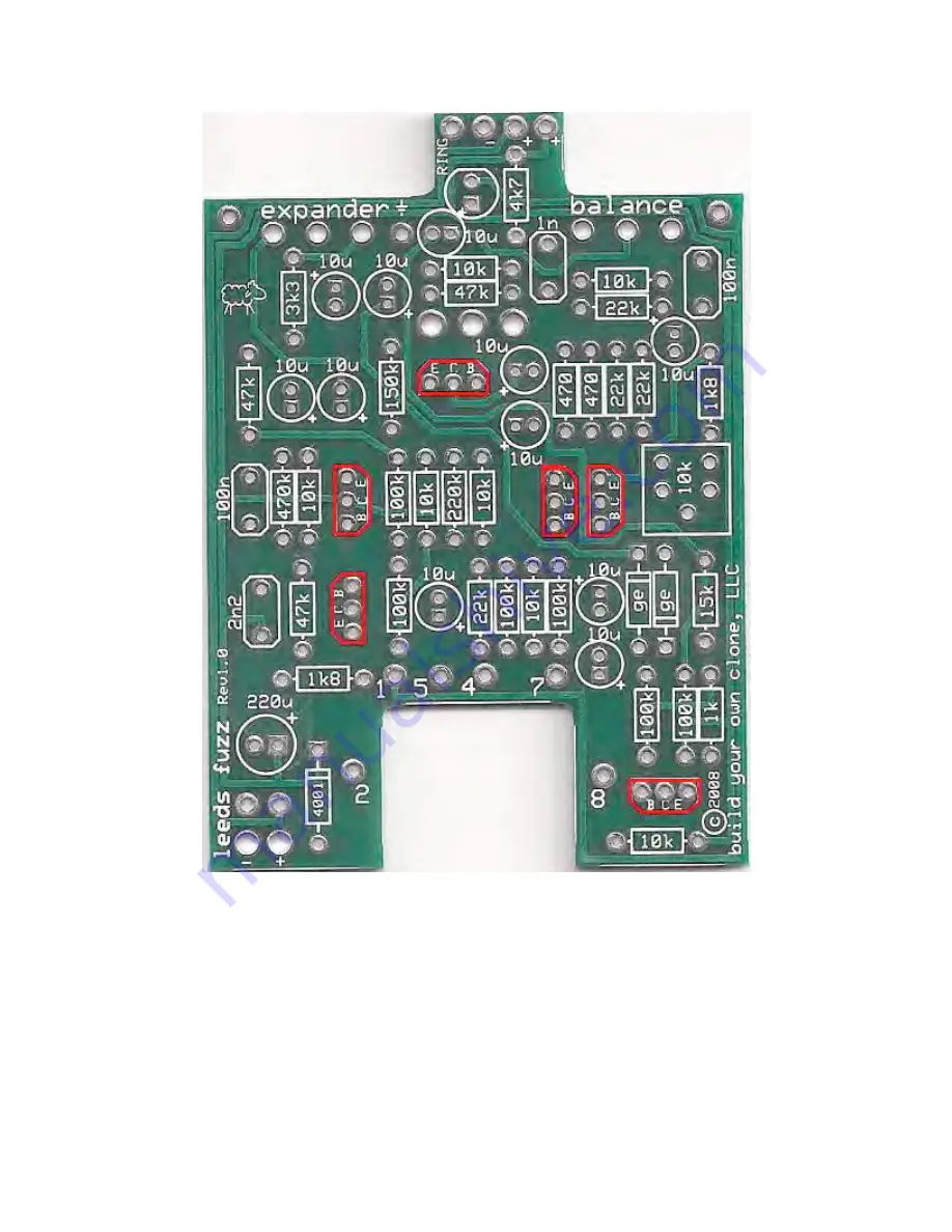
STEP 5: Add the transistors. Match the flat side of the transistor to the flat side of the
layout on the PCB.
Страница 1: ...Please direct all warranty issues to sales buildyourownclone com This would include any missing parts issues Return BYOC LLC accepts returns and exchanges on all products for any reason as long as the...
Страница 2: ...are about to ask may already be answered Here are a list of things that you should include in the body of your tech support thread 1 A detailed explanation of what the problem is not just It doesn t w...
Страница 3: ...Z KIT INSTRUCTION INDEX Parts Checklist page 4 5 Populating the Circuit Board page 6 12 Assembly page 13 15 Wiring the Footswitch Jacks page 16 18 Setting up the Internal Trimpots page 19 Schematic pa...
Страница 4: ...4 22k Red red Black Red Brown Red Red Orange Gold 3 47k Yellow Purple Black Red Brown Yellow Purple Orange Gold 6 100k Brown Black Black Orange Brown Brown Black Yellow Gold 1 150k Brown Green Black...
Страница 5: ...abelled 103 Hardware 1 drilled enclosure w 4 screws 1 byoc Leeds Fuzz circuit board 1 SPDT PC mounted toggle switch 1 3PDT footswitch 2 knobs 1 AC adaptor jack 1 mono jack 1 stereo jack 1 red LED 1 ba...
Страница 6: ...Populating the Circuit Board STEP 1 Add the resistors Resistors are not polarized so it does not matter which end goes in which solder pad...
Страница 7: ...4001 will be black with a silver stripe The Germanium diodes will be clear with a green stripe Be sure to matched the end of the diode with the stripe to the layout on the PCB The stripped end should...
Страница 8: ...STEP 3 Add the film capacitors These are not polarized so they can be inserted into the PCB in either direction...
Страница 9: ...hese because the trimpot itself only has 3 legs but the PCB has 5 holes The PCB has 5 holes so that it can accomodate a variety of different trimpot brands and models There should only be one way the...
Страница 10: ...STEP 5 Add the transistors Match the flat side of the transistor to the flat side of the layout on the PCB...
Страница 11: ...electrolytic capacitors These are polarized The positive end will have a longer lead and should go in the square solder pad The negative end will have a shorter lead with a black strip running down th...
Страница 12: ...the under side of the strain relief holes Insert the stripped ends of the battery snap wires into the topside of their respective solder pads Solder on the bottom side where highlited in yellow Remem...
Страница 13: ...or jack to the eyelet on the PCB with 2 inches of hook up wire Connect the SLEEVE of the DC adaptor jack to the eyelet on the far right side of the PCB with 2 inches of hook up wire Connect the batter...
Страница 14: ...the bottom or solder side is up Insert the two B50K potentiometers the LED and the toggle switch into the bottom side of the PCB DO NOT SOLDER There are only two ways in which the toggle switch can fi...
Страница 15: ...ten them with your fingers You do not want them very tight yet Be sure to keep your hand on the PCB so that it does not fall off the PC mounting posts of the pots and toggle switch Step 5 Turn the ent...
Страница 16: ...the footswitch and jacks Step 1 Install the 1 4 jacks to the enclosure Be sure to turn the OUT jack a 1 4 turn counter clockwise so that solder terminal for the tip does not short out against the enc...
Страница 17: ...lugs eyelets 1 2 7 8 Cut 1 x 1 piece of wire Strip 1 8 off each end This will be used to connect lug eyelet 5 Cut 1 x 1 5 peice of wire Strip 1 8 of one end Strip 1 2 off the other end This will be u...
Страница 18: ...r the footswitch Step 4 Remove the PCB assembly from the enclosure Solder the open ends of the wires that you just soldered to the footswitch to their respective eyelets on the PCB Load the wires in f...
Страница 19: ...as such it can cause an unusual noise gate effect at the end of each note on certain settings Ideally you want to set this trimpot so that it produces the most noise This may seem counterintuitive bu...
Страница 20: ...Please visit...
Страница 21: ...http buildyourownclone com board for any technical support copyright 2009 B Y O C LLC...